W W W . B A L T I M O R E A I R C O I L . C O M . A U
12
M A R 2 0 8 - 0
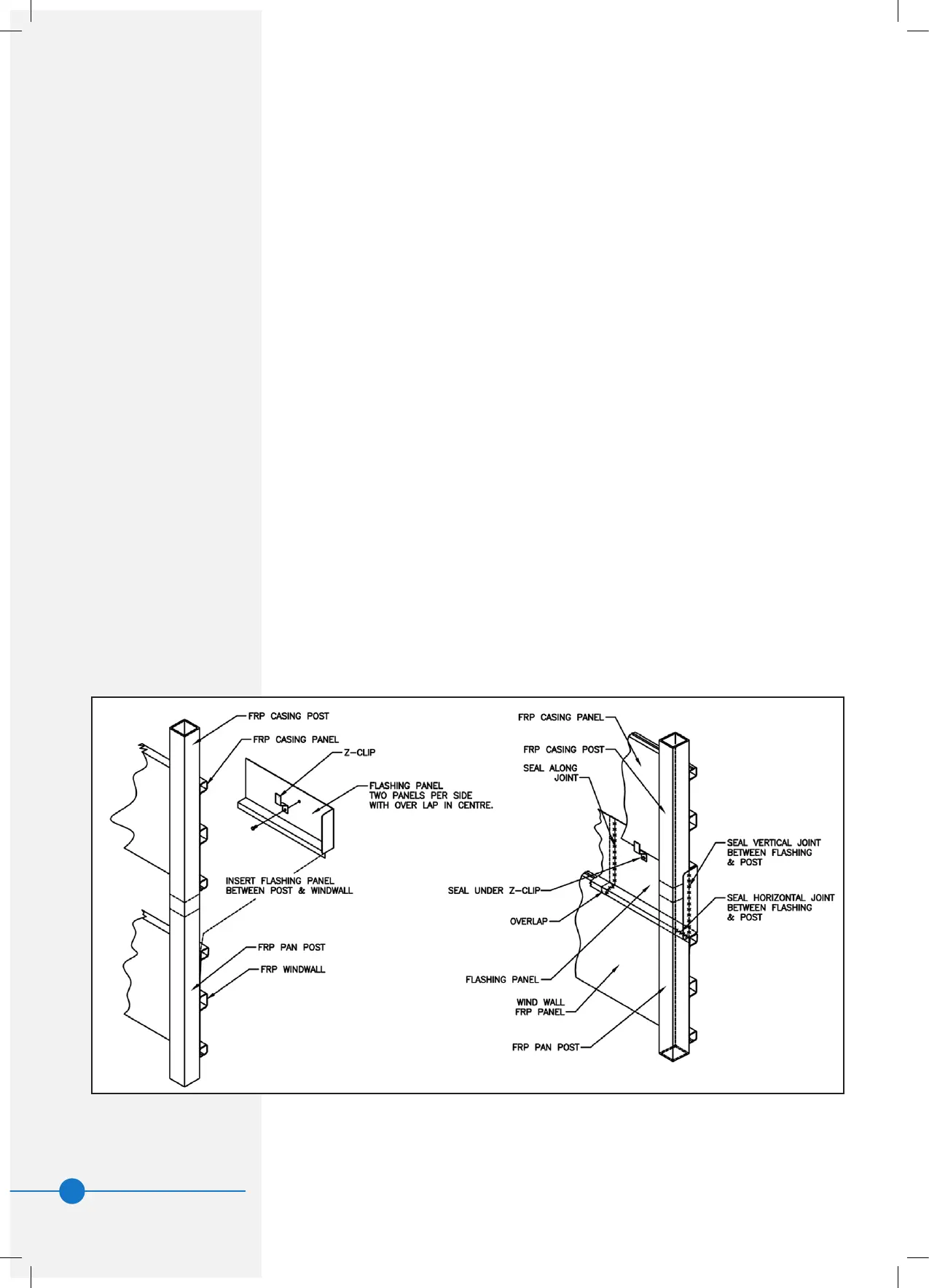
Fitting Of Wind Walls
1. Prior to tting ashing, the following steps in installation should have
taken place: (a) Basin(s) placed in position and shimmed to make level
and carry weight evenly. (b) Casing lowered onto basin legs and the leg
joiners bolted together.
2. With the casing bolted to the basin, seal the joints between the posts.
3. There are two ashing pieces provided for each side of the unit. Each
ashing piece rests on the berglass ledge of the basin wind wall. The
wind wall is not fully glued to the post and can be temporarily pulled
away from the post to slide the ashing in. Each ashing piece has
a folded end to prevent water falling out. When the ashing is in the
correct place, this folded end is sealing against the outside face of the
corner post. The ashing pieces overlap by approximately 30mm. They
are not designed to be bolted together.
4. To x the ashing in position, screw the Z-section brackets to the
ashing pieces so as to pull the ashing against the upper berglass
panel. Sealer is applied to the fastener as it is tted to prevent water
migration through the fastening points.
5. When the ashing is in place, there is a cavity created behind the corner
posts and sealing is required within this area. (a) Use the sealer provided
to seal the bottom horizontal corners behind the post. (b) Seal the
vertical joint between the post and ashing ends.
6. Seal the vertical joint where ashing pieces overlap each other.
7. It is not envisaged that sealing is needed on any of the other horizontal
joints such as where ashing overlaps berglass panels.
Figure 9. Fitting of Wind Walls
 Loading...