W W W . B A L T I M O R E A I R C O I L . C O M . A U
4
M A R 2 0 8 - 0
2
RC SERIES
Unit Rigging & Assembly
NOTE: For weight information,
refer to the submittal drawing
package.
NOTE: Any motors or
accessories shipped in the
cold water basin must be
removed prior to installation.
Rigging
To simplify shipping, rigging and installation all RC Series coil products
are shipped in major sections consisting of a basin assembly(s) and one
or more casing/roof deck sections (see Table 1).
The proper rigging sequence for the RC series is to lift the basin
section(s) into place rst. On multi-section basins lift each section into
place separately and then bolt sections together. Next, lift each casing
section into place and secure to the basin section. If motor(s) are
supplied loose t the motors. At the completion of this stage a crane is
no longer required.
Finally securely bolt the unit to supporting steel and on multi-section
basins seal the joint between sections.
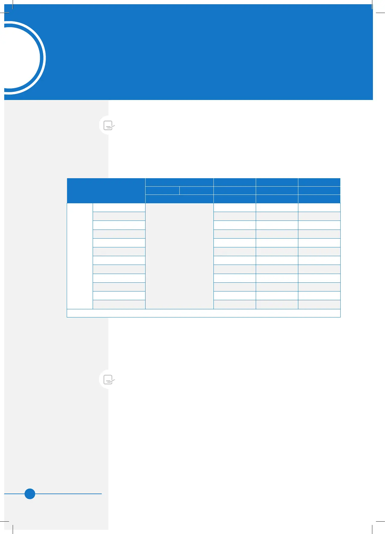
Table 1 gives the recommended dimensions for rigging each section
of any RC series coil product. With the information from the table and
the additional instructions on the following pages the rigging of an RC
series coil product can be quickly accomplished.
Table 1. Recommended Dimensions for Rigging
NOMINAL
BOX
SIZES
No. of H1 H2 L
Basin Casing (g 1) (g 2) (g 2)
Sections (mm) (mm) (mm)
SINGLE FAN UNITS
5’ x 5’
1 each
1200 1700 1500
6’ x 6’ 1600 1900 1800
7’ x 7’ 1900 2200 2100
8’ x 8’ 2200 2500 2400
7’ x 10.5’ 2900 2200 3300
9’ x 9’ 2400 2700 2800
8’ x 12’ 3500 2500 3700
10’ x 10’ 2700 3000 3000
11’ x 11’ 2900 3300 3400
9’ x 13.5’ 4000 2700 4200
10’ x 15’ 4500 3000 4700
11’ x 16.5’ 5000 3300 5100
*** Casing Section Includes Roof Deck (Fan Assembly) ***
 Loading...