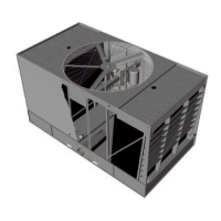
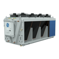
POWER PANEL
At the outside of the power panel, the following components can be found:
• ON/OFF switch
Operating instructions Digital Controller
There are different menu's:
• Main Loop Menu (readout unit status, temperatures, fan speed, etc...)
• Alarms (status of different alarms)
• User Menu (operational settings)
• Manufacturer Menu (not accessible)
• Clock
• System info
• Logger (alarm and warning history)
• Maintenance
• Working time (operating hours fans and adiabatic pre-cooling)
• Inputs/outputs
Please refer to the Software Instructions Manual (SI-TVFC) and the units specific parameter settings in
your submittal package.
CAUTION
Changing the controller's parameters may result in an undesired operation of the unit such as a
'hunting' phenomenon, premature activation of pre-cooling (hence increased water consumption)
or in late pre-cooling activation resulting in fluid outlet temperatures exceeding the design
temperature.
Monitoring of process information
DRY CONTACTS AT TERMINAL STRIP IN ELECTRICAL PANEL
• Input:
- Run authorization (NO)
- Free cooling (NO)
• Output:
- General Alarm (NO+NC)
- Warning (NO)
- Run Indication (NO)
DIGITAL BUS SYSTEM
A bus connection from the digital controller for monitoring can be wired to the terminal strip. Depending on the
required communication protocol, a different optional communications card can be installed in the controller.
W W W . B A L T I M O R E A I R C O I L . E U
14
 Loading...