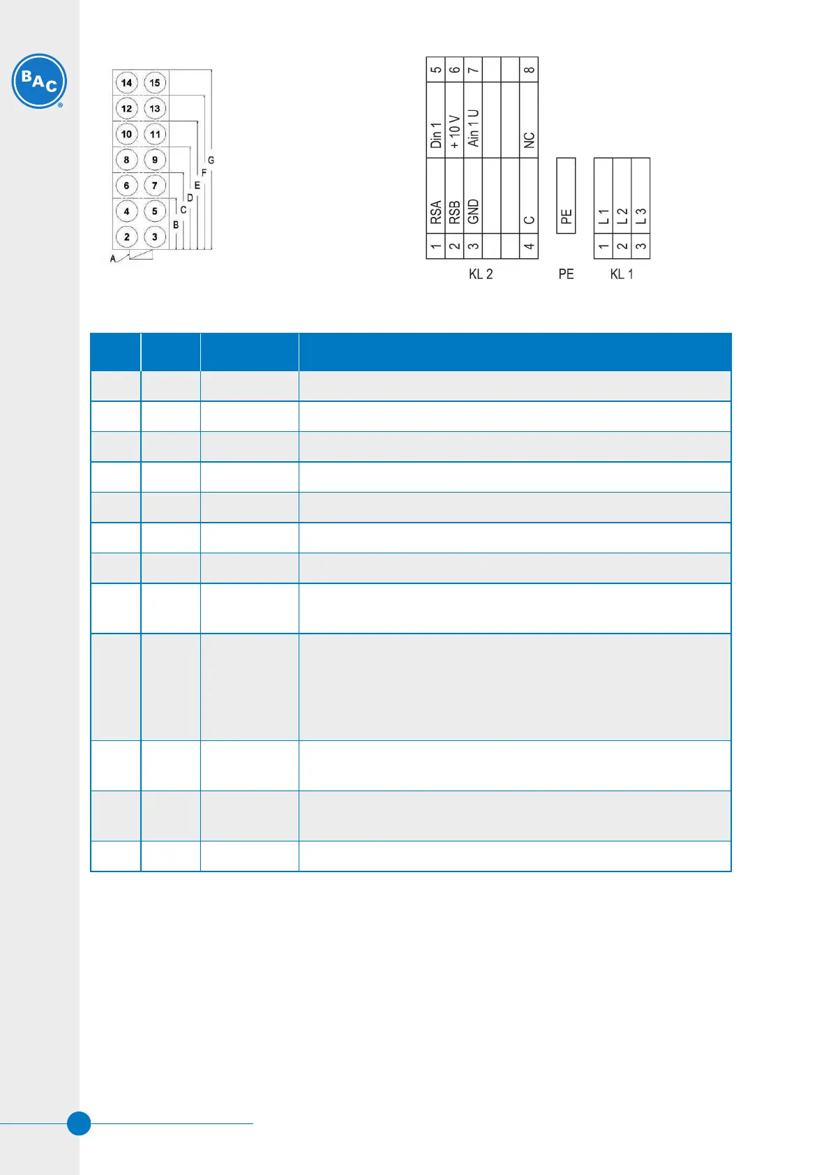
A. Control Panel
B. 4 Fan Unit
C. 6 Fan Unit
D. 8 Fan Unit
E. 10 Fan Unit
F. 12 Fan Unit
G. 14 Fan Unit
Diagram showing sequence of fan motor address Schematic of internal motor terminal strip
No. Conn. Designation Function / assignment
KL 1 1 L1 Mains supply connection, supply voltage 3~380÷480 VAC; 50/60 Hz
KL 1 2 L2 Mains supply connection, supply voltage 3~380÷480 VAC; 50/60 Hz
KL 1 3 L3 Mains supply connection, supply voltage 3~380÷480 VAC; 50/60 Hz
PE PE Earth connection, PE connection
KL 2 1 RSA Bus connection RS-485, RSA, MODBUS RTU; SELV
KL 2 2 RSB Bus connection RS-485, RSB, MODBUS RTU; SELV
KL 2 3 GND Signal ground for control interface, SELV
Kl 2 4 C Status relay; floating status contact; changeover contact; common
connection; contact rating 250 VAC / 2 A (AC1)
KL 2 5 Din1 Digital input 1 enabling of electronics
Enabling: open pin or applied voltage 5-50 VDC
Disabling: bridge to GND or applied voltage < 1 VDC
Reset function: triggers software reset after a level change to <1 V;
SELV
KL 2 6 + 10 V Fixed voltage output 10 VDC, +10V ±3%, max. 10 mA, short circuit-
proof, power supply for external devices (e.g. potentiometer), SELV
KL 2 7 Ain U Analogue input 1 (set value) 0-10 V, Ri=100 kΩ, parametrizable
curve, only usable as alternative to input Ain1 SELV
KL 2 8 NC Status relay, floating status contact, break for failure
Legend for internal motor terminal strip
W W W . B A L T I M O R E A I R C O I L . E U
20
 Loading...