WWW.BALTIMOREAIRCOIL.COM
16
Installation of the Pressure Regulating Valve
As part of the Water Monitoring option, a pressure regulating valve (PRV) is supplied.
Follow the instructions for installation. The valve must be installed on straight rigid pipe
7.5” (19 cm) from the make-up valve, refer to the diagram below for more information.
Direction of Flow
Minimum of 10 Inlet
Pipe Diameters from
PRV to First Turn
Minimum of 20 Inlet
Pipe Diameters from
PRV to First Turn
Set to 20 psi
Figure 16. Pressure Regulating Valve
Ammonia Installation Instructions
If using ammonia, on TSDC models the following additions are recommended to ensure
integrity and cleanliness of the microchannel coil:
• Discharge strainer (provided by others) on the discharge line from the compressor to
the TrilliumSeries™ Adiabatic Condenser as close to the unit as possible. The strainer
will catch weld slag and other system impurities during start-up. Suggested strainers
are Danfoss FIA 50 with a 100 mesh strainer or finer.
• Filter dryer for the ammonia in the exiting liquid line, such as Parker C-40016-P
replaceable core filter dryers or similar. This eliminates any moisture in the ammonia.
• Autopurger installed to eliminate any non-condensables.
Customer Electrical Connections
• Customer connection of 3 phase power and earth/ground is within the isolator/
disconnect. Ensure correct voltage is supplied to the unit. Refer the submittal in the
Customer Information Packet for this information.
• The connection of the above items will allow the TrilliumSeries™ Adiabatic Product
to operate as specified. Please see the following sections for further details and see
“Wiring and Electrical Information” on page 17.
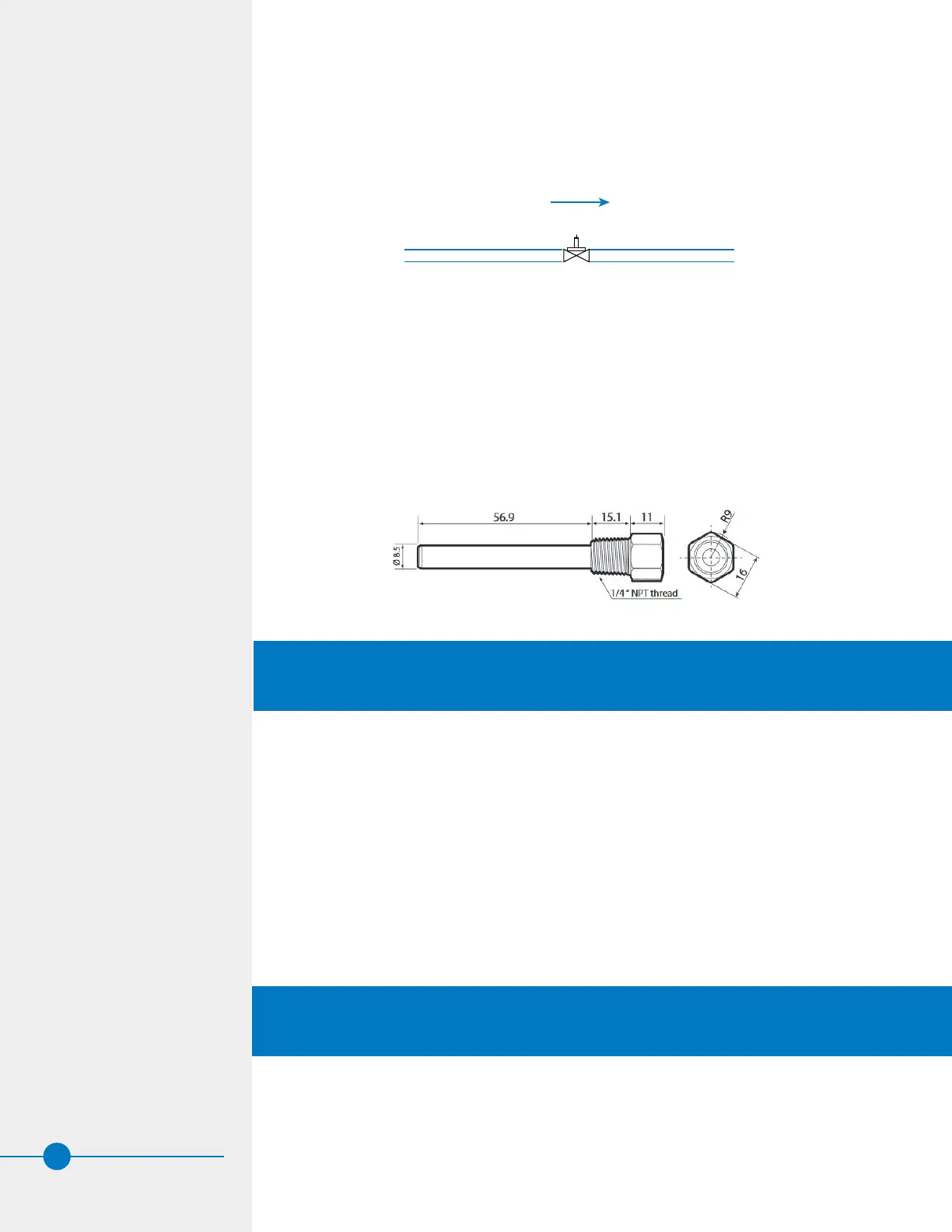
Installation of Leaving Fluid Temperature Sensor (TSDF2 Fluid Cooler Models Only)
As part of the self-contained Temperature Control Package, a leaving water temperature
sensor is supplied with a socket for installation in the piping leaving the unit. The sensor
should be installed at least 10 times the pipe diameter from curves in the piping. The socket
is equipped with a PG7-IP68 cable gland applied to the hexagonal end to secure the cable.
Figure 17. Leaving Fluid Temperature Sensor
 Loading...