MGS Series Controller Manual
24 6709-9000 Rev 1
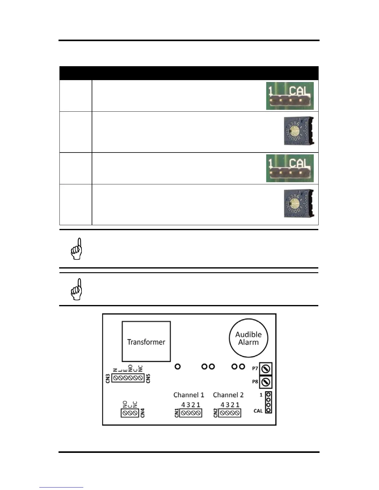
4.4. Changing Alarm Level for 2-Channel, 2-Alarm Units
Step Instructions
1
Connect voltmeter leads to pin 4 (-Ve) and
pin 1 (+Ve) on the CAL header.
2
Using the flat-blade screwdriver, adjust
potentiometer P7 until the reading on the DC
voltmeter corresponds to the desired input
high alarm level.
P7
3
Connect voltmeter leads to pin 4 (-Ve) and
pin 2 (+Ve) on the CAL header.
4
Using the flat-blade screwdriver, adjust
potentiometer P8 until the reading on the DC
voltmeter corresponds to the desired input
low alarm level.
P8
NOTE: When adjusting the alarm level, a 0.4 to 2.0 VDC
reading on the voltmeter corresponds to a 4 to 20 mA value
for the input alarm threshold.
NOTE: Both channels have the same alarm thresholds.
Figure 13. Hardware PCB Layout (2 Channel, 2 Alarm)
 Loading...