INTRODUCTION
Used in conjunction with any Badger Meter impeller flow monitor or transmitter, Badger Meter non-magnetic flow sensors
provide an accurate rate of liquid flow as well as total accumulated flow. A number of sensor models are offered, which cover
applications for a wide range of pipe sizes and pressure/temperature specifications.
The flow sensors generate a frequency which is proportional to flow rate. An internal preamplifier allows the pulse signal to
travel up to 2000 feet without further amplification. Power to operate the sensor is provided by the flow monitor. The impeller
bearing assembly, shaft and O-rings are replaceable in the field.
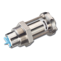
Badger Meter flow sensors feature a closed, six-bladed impeller design, using a proprietary, non-magnetic sensing
technology. The forward-swept impeller shape provides higher, more constant torque than four-bladed impeller designs,
and is less prone to fouling by water-borne debris. The forward-curved shape, coupled with the absence of magnetic
drag, provides improved operation and repeatability, even at lower flow rates. As the liquid flow turns the impeller, a low
impedance signal is transmitted with a frequency proportional to the flow rate.
Sensors of similar type are interchangeable, so there is no need for recalibration after servicing or replacement.
This manual provides instructions for the following insertion style flow sensors, as indicated:
220BR; 220SS; 220PV; 225BR; 226BR; 226SS
CERTIFICATION
MECHANICAL INSTALLATION
Flow measurement accuracy for all flow measuring devices is highly dependent on proper location in the piping system.
Irregular flow velocity profiles caused by valves, fittings, and pipe bends can lead to inaccurate overall flow rate indications
although local flow velocity measurement may be accurate. A sensor located where it can be affected by air bubbles, floating
debris, or sediment may not achieve full accuracy and could be damaged. Badger Meter flow sensors are designed to operate
reliably under adverse conditions. Follow these recommendations to provide maximum system accuracy:
• Choose a location along the pipe where 10 pipe diameters upstream and 5 pipe diameters downstream of the sensor
provide no flow disturbance. Pipe bends, valves, other fittings, pipe enlargements and reductions should not be present in
this length of pipe.
• The preferred location around the circumference of a horizontal pipe is on top. If trapped air or debris will interfere, then
the sensor should be located further around the pipe from the top but not more than 45 degrees from top center. The
sensor should never be located at the bottom of the pipe, as sediment may collect there. Locations off top center cause
the impeller friction to increase, which may affect performance at low flow rates. Any circumferential location is correct for
installation in vertical pipes.
• Allow an insertion depth of 1-1/2 inches (38 mm) for pipe sizes 2-1/2 inches and larger for accurate flow rate calibration.
Detailed installation instructions for various sensor mounting configurations on the following pages include methods for
providing correct insertion depth.
• Align the sensor so that the impeller rotation is parallel to flow. Alignment instructions are included on the
following pages.
Introduction
Page 3 February 2018 SEN-UM-01635-EN-11
 Loading...