INSTALLATION FOR 220BR, 220SS, 220PV
Installation Procedure
The insertion depth and alignment of the flow sensor assembly are critical to the accuracy of the flow measurement. The flat
end of the sensor sleeve assembly MUST BE INSTALLED 1-1/2 inches (38 mm) from the inside wall of the pipe. To allow for
variations in wall thickness, lining, or coatings, the depth adjustment is controlled by the position of the hex nuts on the three
threaded studs of the hex mounting adapter. The hex mounting adapter is provided with a 2 inch male NPT connection.
There are two methods of mounting these sensors in a 2-1/2 inch or larger pipe. One is with a 2 inch NPT threaded pipe
saddle. The other is with a welded-on fitting such as a Thredolet®, also tapped for a 2 inch NPT connection. In either case, cut a
2 inch (51 mm) hole through a depressurized pipe and then secure the saddle or weld-on fitting to the pipe. (For drilling into
a pressurized pipe, see "Installation into a Pressurized Pipeline" on page 7.) Install the 2 inch NPT adapter provided, using a
thread sealant to prevent leakage. Tighten as necessary. Badger Meter insert style flow sensors are calibrated with the sensor
inserted 1-1/2 inches (38 mm) into the pipe flow.
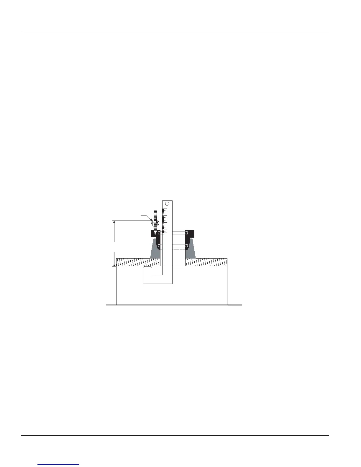
To determine the proper insertion depth, follow these steps:
1. Apply anti-seize thread lubricant (supplied with the sensor) to the threaded studs of the mounting adapter.
2. Insert the depth gauge into the mounting adapter and set it against the inside wall of the pipe as shown in Figure 1. Set
the top of the upper adjusting nut to 3-3/4 inches (95 mm) as measured. Lock it in place with the bottom nut on the same
stud. Repeat for the other adjusting nuts.
OTE:N For Model 220PVS, set the nuts 6-1/2 inches (165 mm) above the inside wall of the pipe.
3 ¾”
20345
Adjusting Nuts
Figure 1: Installation for 220BR and 220SS
3. Clean the O-rings and the ow sensor sleeve, and lightly lubricate the O-rings with silicone grease from the packet
provided (or another acceptable lubricant). Take care not to get grease on the impeller or bearing.
4. Insert the ow sensor into the 2 inch NPT adapter so that the mounting holes in the positioning collar t over the studs on
the adapter.
5. Lower the sensor onto the previously adjusted nuts. Install the lock nuts on top of the positioning collar and tighten. Now
tighten the lower jam nuts rmly against the upper adjusting nuts to secure them for future removal of the sensor for
inspection or service.
Installation for 220BR, 220SS, 220PV
Page 4 February 2018SEN-UM-01635-EN-11
 Loading...