Installation if the Pipe is Depressurized and Drained
1. Drill or cut a hole in the pipe with a 1-7/8 inch (48 mm) drill or hole saw. Note the pipe wall thickness for use in calculating
sensor assembly depth. A location on the top of the pipe is best for overall performance and service life; however,
any radial location on the top half of the pipe is acceptable. Allow a minimum of 10 pipe diameters upstream and 5
downstream from the sensor of straight unobstructed pipe to allow full development of the ow prole.
2. Install either a service saddle or welded pipe tting (2 inch female NPT) on the outside diameter of the pipe over the 1-7/8
inch (48 mm) hole.
3. Install the Badger Meter isolation valve and nipple onto the tting using pipe thread sealant or Teon® tape on all threads.
4. Install the Badger Meter hex mounting adapter onto the valve assembly. Use pipe thread sealant on the adapter.
5. Tighten the hex mounting adapter so that no stud is aligned with the center-line of the pipe. This could interfere with nal
sensor alignment.
6. Measure the depth and set the height of the nuts of the hex mounting adapter.
OTE:N Badger Meter recommends that you purchase a Hot Tap insertion/removal Tool (Model HTT) for future service,
even if the sensor is installed in a drained system. The Model HTT allows you to remove the sensor sleeve
assembly from the pipe line without draining the entire loop where the sensor is mounted.
7. In a fully depressurized and drained pipe, the sensor tube assembly may be installed by hand. If reinstalling into a drained
system thought to have been depressurized and drained, verify by very slowly opening the isolation valve.
a. Carefully and very slowly open the isolation valve to relieve any pressure that may have built up.
b. Fully open the isolation valve.
c. Push the sensor sleeve into the pipe with a slight twisting motion.
d. Guide the sensor collar holes over the three hex adapter studs until the collar rests on the nuts. Hex nuts should have
been previously set to the correct height.
e. Install the three lock nuts onto these studs at the top of the positioning collar and securely tighten.
8. Loosen the two set screws in the positioning collar with a 3/32 inch Allen wrench.
9. Align the sensor sight holes along the pipe axis using the alignment rod from the sensor installation kit. M
10. Verify that the ow label arrow on the sensor matches the liquid ow direction inside the pipe.
11. Tighten the positioning collar set screws.
OTE:N As a backup to the flow label arrow, there is a small hole located beside one of the sight holes to also indicate the
upstream side of the sensor.
Installation into a Pressurized Pipeline
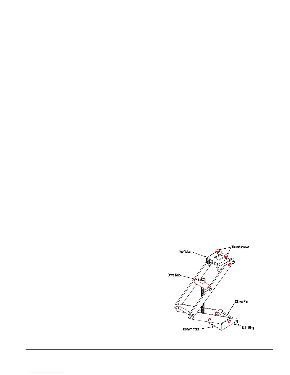
The Model HTT (Hot Tap Tool) provides the mechanical
advantage required to safety insert and remove a
Badger Meter hot tap flow sensor from line pressure, and
provides a restraint when removing the sensor from a
pressurized pipe.
Refer to Figure 3 for identification and location of the HTT
parts described in this section.
For pipe sizes 2-1/2 inch and above, all Badger Meter sensors
are inserted 1-1/2 inches (38 mm) from the inside wall of the
pipe. The insertion depth is controlled by the position of the
hex nuts on the three threaded rods.
To calculate the distance (D) between the top of the sensor
hex mounting adapter and the bottom of the positioning
collar (the top of the hex nut), ADD the H dimension, pipe
wall thickness, and insertion depth, and SUBTRACT the total
from the overall sensor length. See the example and formula
on the next page, and refer to Figure 4.
Figure 3: Model HTT (Hot Tap Tool)
Hot Tap Installation for 225BR, 226BR, and 226SS
Page 7 February 2018 SEN-UM-01635-EN-11
 Loading...