Alignment of Flow Sensor
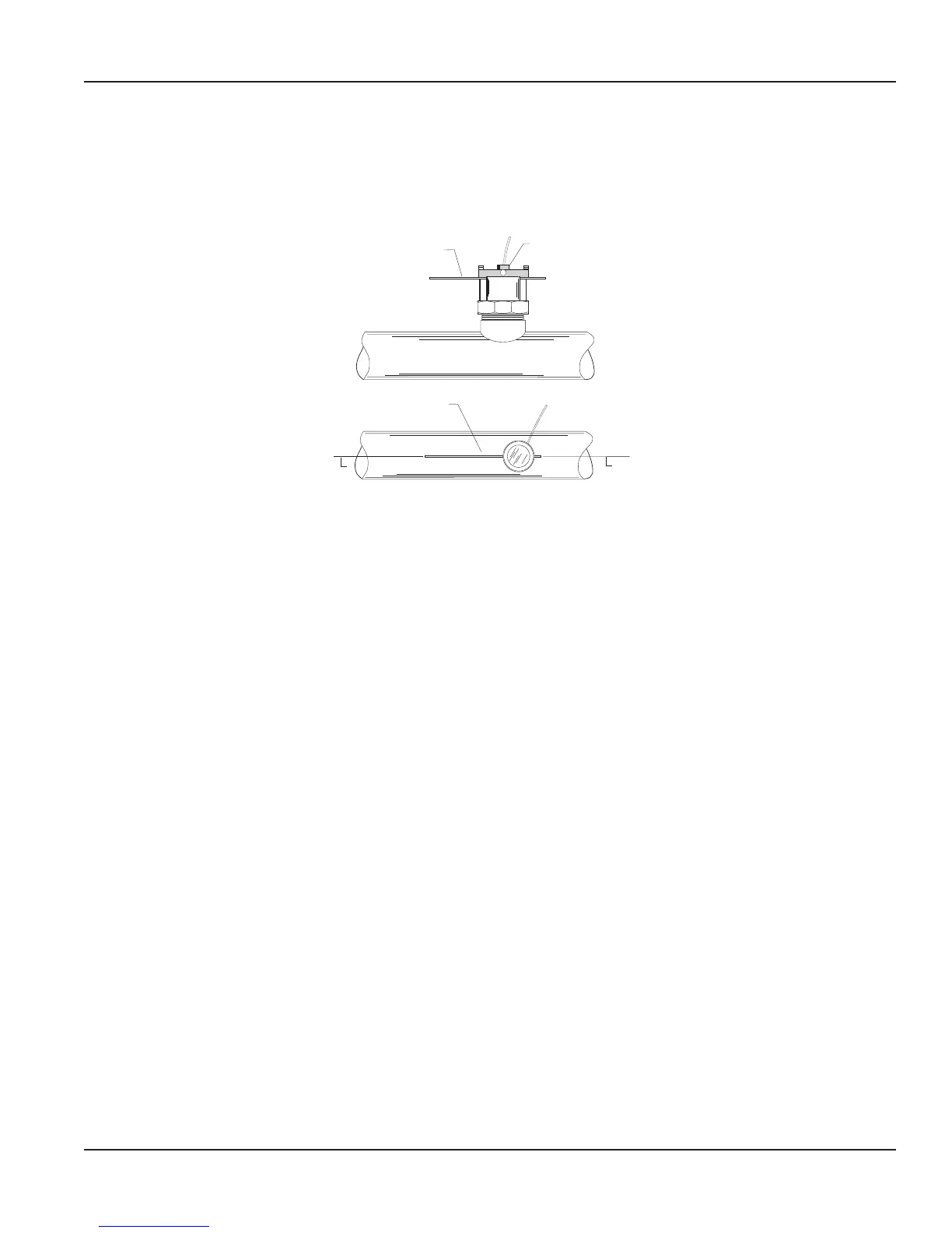
1. Loosen the positioning collar set screws with a 3/32 inch Allen wrench. Place the alignment rod through the sight holes in
the ow sensor. See Figure 2. Using the alignment rod as a guide, align the ow sensor so the ow label arrow matches the
pipe ow direction and the alignment rod is exactly parallel to the pipe. This procedure aligns the impeller directly into the
uid ow.
SET SCREW
ALIGNMENT ROD
ALIGNMENT ROD
C
C
Figure 2: Alignment of Flow Sensor 220BR and 220SS
2. As a backup to the ow arrow label, there is a small hole next to the larger sight hole of the upstream side. With a
3/32 inch Allen wrench, tighten the positioning collar set screws.
3. Double check that the sight holes in the sleeve are parallel down the pipe and the ow arrow label matches the pipe liquid
ow direction.
4. Cable routing: The positioning collar is threaded for connection of a standard 1/2 inch electrical conduit (ex cable) or a
wire strain relief. Route the cable as required. Be sure to leave enough ex in the cable or conduit to allow future removal
of the sensor for service or cleaning.
Hot Tap Installation for 225BR, 226BR, and 226SS
Page 5 February 2018 SEN-UM-01635-EN-11
 Loading...