ELECTRICAL INSTALLATION
OTE:N If the sensor has white and black wires instead of red and black, connect the white wire wherever red is indicated.
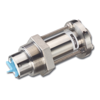
Standard Sensors
The metal collar on top of the 220 sensors or an optional conduit cap on the Series 250 sensors will accept 1/2 inch threaded
conduit fittings.
1. Route the cable from the sensor to a Badger Meter ow monitor/transmitter. The cable can be extended up to 2000 feet,
using 2-conductor shielded 20 AWG or larger stranded copper wire. Be sure to leave enough exibility in the cable or
conduit to allow for future service of the ow sensor, if necessary.
2. When connecting to a Badger Meter ow monitor/transmitter, locate the section of terminal strip on the monitor labeled
SENSOR INPUT or SENSOR. Connect the red (or white) wire to IN, SIGNAL(+) or SIGNAL terminal, connect the black wire
to GND, SIGNAL(-) or COM terminal, and connect the shield drain wire (if applicable) to SLD.
OTE:N When interfacing with other equipment, consult the manufacturer for input designations. The signal wave forms and
power requirements are described in "Specifications" on page 18. See additional technical literature in the Resource
Library at www.badgermeter.com.
IR Sensors
OTE:N The sensor leads are supplied with watertight caps over the ends. DO NOT remove the plastic caps from the sensor
leads until ready to splice.
1. Use a twisted pair cable suitable for direct burial to connect the sensor to the transmitter, monitor, or controller. Multi-pair
telecommunication cable or direct burial cables can be used.
2. Make a watertight splice. Two-part epoxy type waterproof kits are recommended. Be sure the epoxy seals the ends of the
cable jacket. Make sure the epoxy is hardened before inverting the splice or dropping it in standing water.
OTE:N Do NOT make an underground splice unless absolutely necessary.
3. Route the cable from the sensor to a Badger Meter ow monitor/transmitter. The cable can be extended up to 2000 feet,
using 2-conductor shielded 20 AWG or larger stranded copper wire with appropriate ratings. Be sure to leave enough
exibility in the cable or conduit to allow for future service of sensor, if necessary.
4. When connecting to a Badger Meter ow monitor/transmitter, locate the section of terminal strip on the monitor labeled
SENSOR INPUT or SENSOR. Connect the red (or white) wire to IN, SIGNAL(+) or SIGNAL terminal, connect the black wire
to GND, SIGNAL(-) or COM terminal, and connect the shield drain wire (if applicable) to SLD.
OTE:N When interfacing with other equipment, the signal wave forms and power requirements are described in
"Specifications" on page 18. See additional technical literature in the Resource Library at www.badgermeter.com.
Electrical Installation
Page 10 February 2018SEN-UM-01635-EN-11
 Loading...