64
THE ALDE HEATING SYSTEM
THE ALDE HEATING SYSTEM
HEATING SYSTEMS
alde heating SyStemS
Always replace the heat transfer
fluid (HTF) in accordance with the
antifreeze product’s lifespan. If in any
doubt, replace the HTF after 2 years.
The corrosion inhibitors found in ethylene
glycol antifreeze may not be cross-compatible.
When topping up or replacing the HTF ensure
the new antifreeze is compatible with the
current antifreeze product. Read the product
label or contact the product manufacturer for
details.
operating inStructionS
3020 Compact High Efficiency Boiler
These instructions are approved for the Alde
3020 Compact HE Boiler fitted in motorhomes
in accordance with CE 0402 no. SC0653-13 and
have the E5 mark for installation in vehicles in
accordance with ECE R122, no. 00 001 and R10,
no. 04 166, for use in central heating and hot
water systems.
The boiler is not intended for use by persons
(including children) with reduced physical
sensory or mental capabilities, or lack of
experience and/or knowledge, unless they have
been given instruction or are supervised.
The term “specified use” also covers
observance of the operating and installation
instructions.
The Alde 3020 Compact HE boiler must be
installed or repaired by a competent person in
accordance with current local regulations.
In the unlikely event that your boiler develops
a fault, switch off the boiler and contact Alde,
or your dealer or installer.
Operating and installation instructions for the
Alde control panel are supplied separately.
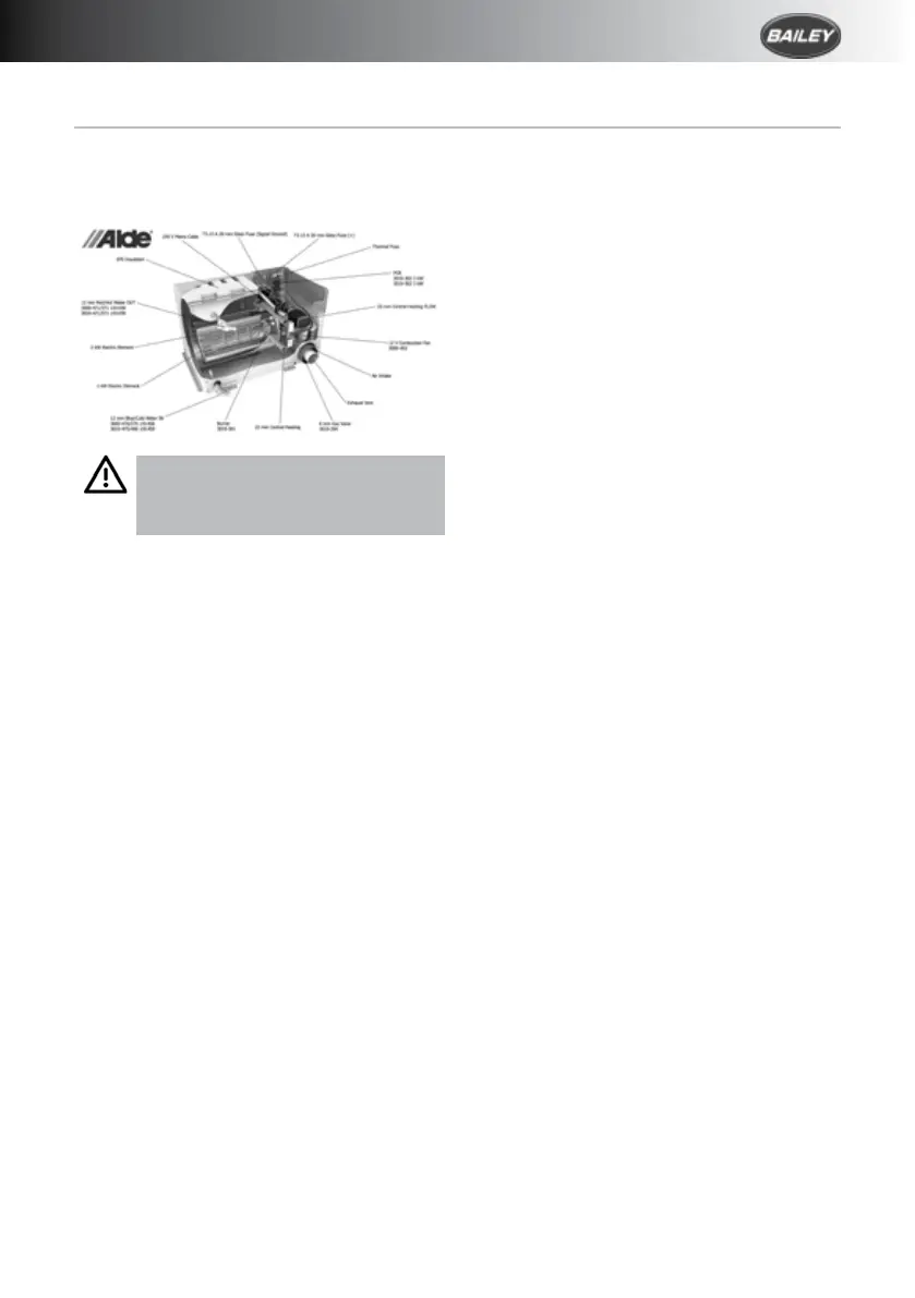
Boiler deSign
The boiler’s internal heat exchanger consists
of three concentric cylinders: the combustion
chamber, the central heating cylinder and the
hot water cylinder.
The combustion chamber is made from
aluminium and is divided into two halves by a
baffle plate, with the burner head located in
the top half and the flue gases venting through
the bottom half.
The combustion assembly is fixed to the end of
the internal heat exchanger. It consists of the
burner, combustion fan, gas valve, air intake,
exhaust ducts and gas line.
Two electric heating elements are sealed inside
the central heating cylinder, one for 1kW, one
for 2kW.
deScription of functionS
gaS heating
When gas heating is set to “On” the
combustion fan starts to revolve. Once the
correct speed is achieved (in RPM), a signal
is sent to the PCB (printed circuit board)
for the burner to be lit. The gas valve opens
passing gas and the ignition module on the
PCB generates sparks at the electrode on the
burner head.
When the burner ignites a flame supervision
device (FSD) signals the ignition module to
cease sparking. The burner fires until the boiler
or room thermostat reach the set-point.
Should the burner flame out unexpectedly, the
FSD detects this and attempts to reignite (for
about 10 seconds), before shutting down and
raising a fault code.