INSTALLATION
DIPSWITCH AND JUMPER SETTINGS
WBPEEUI240756A0 3 - 3
DIPSWITCH AND JUMPER SETTINGS
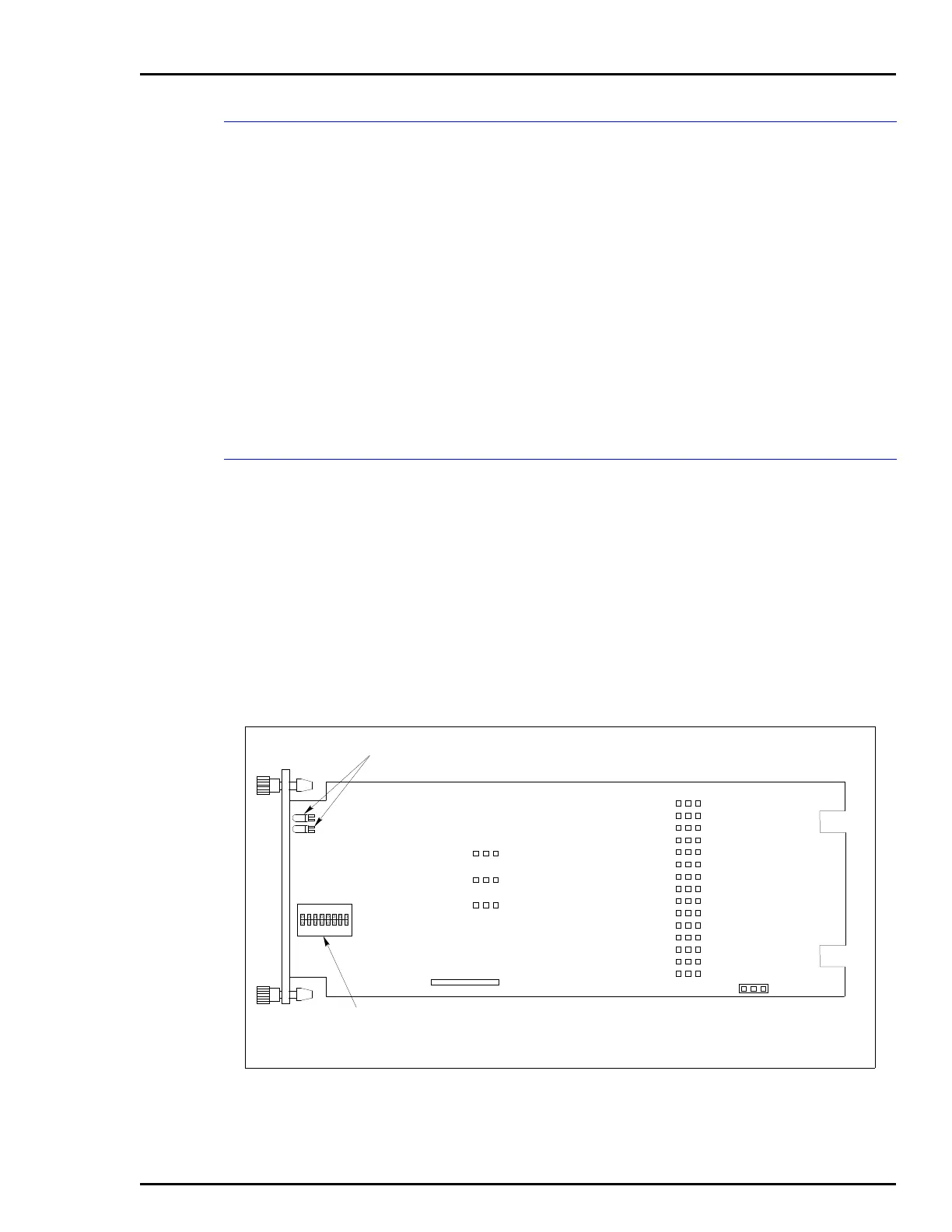
For the IMFEC12 module, there is one dipswitch (S1, Fig. 3-1
is the same for both the IMFEC11 and the IMFEC12) that must
be set before installing the module. The single dipswitch sets
the I/O expander bus address.
For the IMFEC11 module, there is one dipswitch (S1) and 18
jumpers (J2-J4 and J6 -J20) that must be set before installing
the module (Fig. 3-1). The single dipswitch sets the I/O
expander bus address. Jumpers J2 through J4 set the operat-
ing and communication mode, and jumpers J6 through J20
select the input (voltage/current).
NOTE:
Input jumpers (J6 through J20) must be set to the voltage
position (Fig. 3-1) when using a NTAI05 termination unit, a NIAI04
termination module or the NTFB01 field bus termination unit.
Module Address Selection Switch (S1)
The
FEC module must have a unique address on the I/O
expander bus. The FEC module can have one of 64 addresses
(zero to 63). This address identifies the FEC module to the con-
trol module and must be the same as the address set in the
control module setup data (function code 132, specification
S1). Set the address with the eight-position address dipswitch
(S1) shown in Figure 3-1. Switch positions three through eight
of S1 set the six-bit address. Positions one and two must
remain in the closed position. Refer to Table 3-2 for examples
of address settings. Record the I/O expander bus address of
the FEC module in the space provided.
Figure 3-1. IMFEC11/12 Switch and Jumper Locations
P1
P2
J1
P3
T00918A
S1
ADDRESS SWITCH
LEDS
FBS
ON
P-P
ASI
OFF
FB
LCD
J4
J2
J3
J17
CURRENTVOLTAGE
J6
J7
J8
J9
J10
J11
J12
J13
J14
J15
J16
J18
J19
J20
1 2 3 4 5 6 7 8
ON