INTRODUCTION
WBPEEUI240756A0 C - 1
APPENDIX C - NTFB01 TERMINATION UNIT CONFIGURATION
INTRODUCTION
The IMFEC11 module must use the NTFB01 termination unit
to terminate FSK digital smart transmitters on a field bus. All
inputs must be in an FSK digital field bus mode when using
the NTFB01 termination unit. There are no other input types
available when operating in this mode.
CONNECTING INPUTS TO THE NTFB01 TERMINATION UNIT
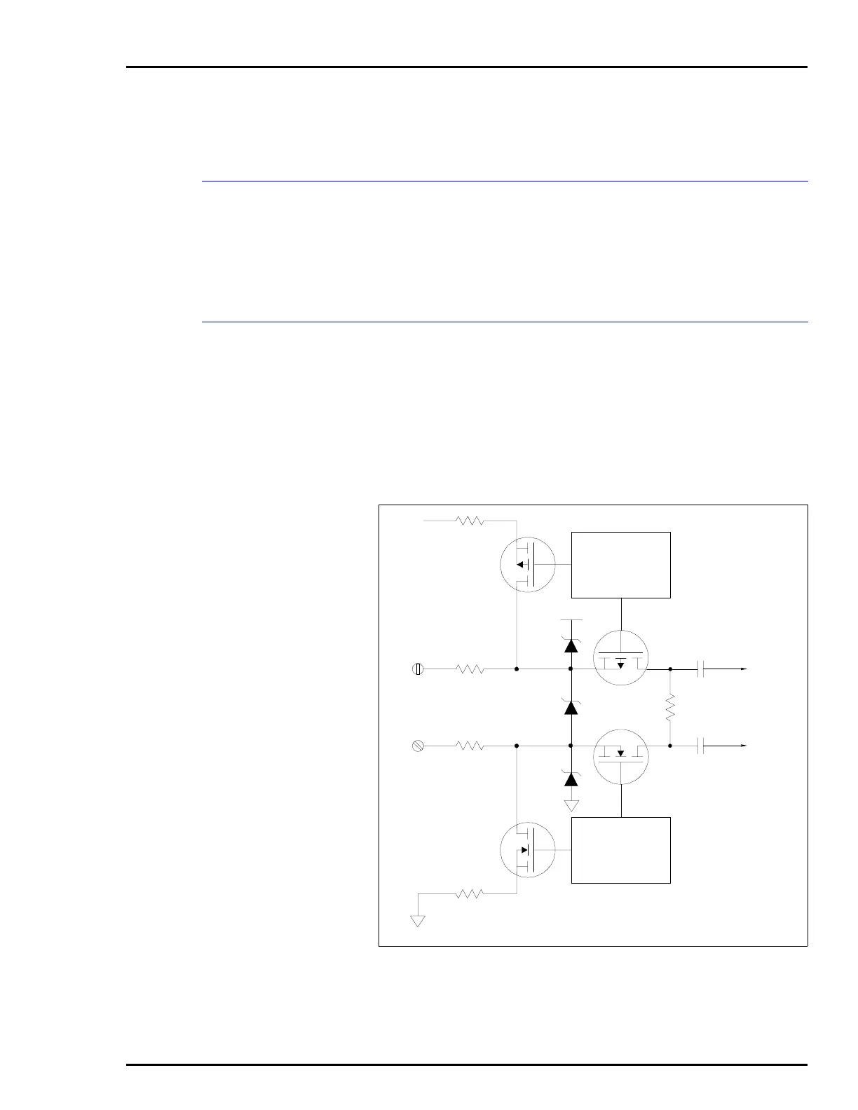
Figure C-1 shows a simplified circuit diagram of the input sig-
nal path through the field bus termination unit. Figure C-2
shows NTFB01 terminal assignments and Figure C-3 shows
module to termination unit cabling.
NOTE:
Input jumpers J6 through J20 on the IMFEC11 board must
be set to the voltage position. Refer to
IMFEC11 Input Jumpers (J6
through J20)
in Section 3.
Figure C-1. NTFB01 I/O Module Input Circuit
CURRENT LIMITING
OR
COMMUNICATION
DISCONNECT
CONTROL
CURRENT LIMITING
OR
COMMUNICATION
DISCONNECT
CONTROL
T00925A
+24 V
+24 V
FB+
FB-
TO IMFEC11
MODULE
FSK+
FSK-