INTRODUCTION
WBPEEUI240756A0 B - 1
APPENDIX B - NIAI04 TERMINATION MODULE CONFIGURATION
INTRODUCTION
The IMFEC1
module can use the NIAI04 termination module
for termination in point-to-point applications. Select the input
type of each channel through dipswitches on the NIAI04 termi-
nation module. The FEC module can accept inputs of 4 to 20
milliamps, 1 to 5 VDC, 0 to 1 VDC, 0 to 5 VDC, 0 to 10 VDC
and -10 to +10 VDC.
CONFIGURING INPUTS
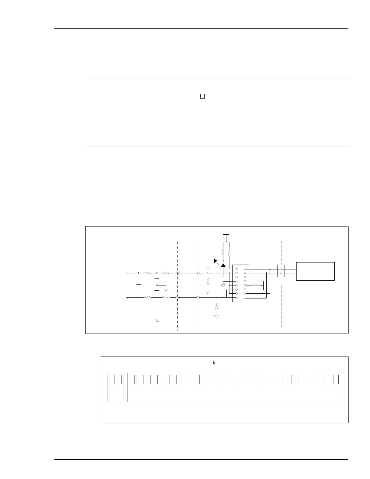
Figure B-1 shows the field input path through an NIAI04 ter-
mination module. Figure B-2 shows the terminal assignments.
Table B-1 shows dipswitch settings. Figure B-3 shows FEC
module to termination module cabling.
NOTE:
Input jumpers J6 through J20 on the IMFEC11 board must
be set to the voltage position. Refer to
IMFEC11 Input Jumpers (J6
through J20)
in Section 3.
Figure B-1. NIAI04 Input Circuit
Figure B-2. NIAI04 Terminal Assignments
MULTIPLEX
CIRCUIT
TO
A/D CONVERTER
FIELD INPUTS
AND
POWER SUPPLY
1
2
3
4
5
6
7
8
TERMINAL
BLOCK
TERMINATION UNIT NIAI04
NKTM01
OR
NKTU02INPUT CIRCUIT
+
-
TERMINAL NUMBER
ANALOG INPUT NUMBER
TP35749A
1 2 3
15 13 12 11 10 914 8 7 6 5 4 3 2 1
5 6 7 8 9 10 11 12 13 14 15 16 17 184 19 20 21 22 23 24 25 26 27 28 29 30 31
–– – – – – –– – – – – – – –
32
+++ + + + + ++ + + + + ++
COMMON
+24 VDC
NOTE: THE DIPSWITCH ANALOG INPUT (AI) NUMBERS AI1-AI15
CORRESPOND NUMERICALLY TO THE ANALOG INPUT NUMBER.