3-14 Receiving & Installation MN715
Size C2 Single Phase Power Installation
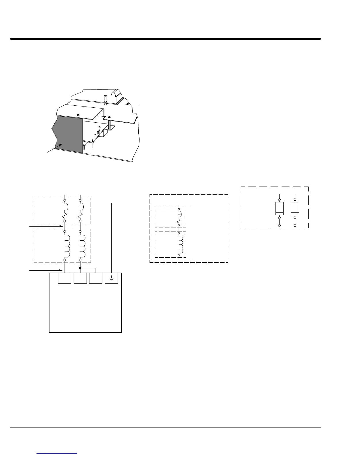
Jumper Configuration
Locate the Interface board, and place JP7 on pins 2 & 3 for single phase operation.
Figure 3-7 Jumper Configuration
JP7
Pins 1 & 2 = Three Phase
Pins 2 & 3 = Single Phase
Bend plastic insulator upward
to access the Interface Board.
JP7
Control Board
Interface Board
Figure 3-8 Size C2 Single Phase 230/460VAC Power and Motor Connections
L1 L2
L1 L2 L3
* Circuit
Breaker
Earth
See Recommended Tightening Torques in Section 6.
Note 3
Baldor
Series 15H
Control
*Optional
Line
Reactor
Note 1
Note 3
A1 B1
A2 B2
Note 4
Notes:
1. See “Protective Devices” described previously in this section.
2. Use same gauge wire for Earth ground as is used for L1, L2 and L3.
3. Metal conduit should be used. Connect conduits so the use of a
Reactor or RC Device does not interrupt EMI/RFI shielding.
4. See Line/Load Reactors described previously in this section.
Note 2
L1 L2
* Fuse
Connection
Note 1
* Optional components
not provided with control.
A1 B1
L1 Neutral
* Circuit
Breaker
*Line
Reactor
A1
A2
Single phase 2 wire ConnectionsSingle phase 3 wire Connections

 Loading...


