VIGIL3 Voice Alarm
Overview, Architecture and Configuration
14 VIGIL3 Overview, Architecture & Configuration issue 2
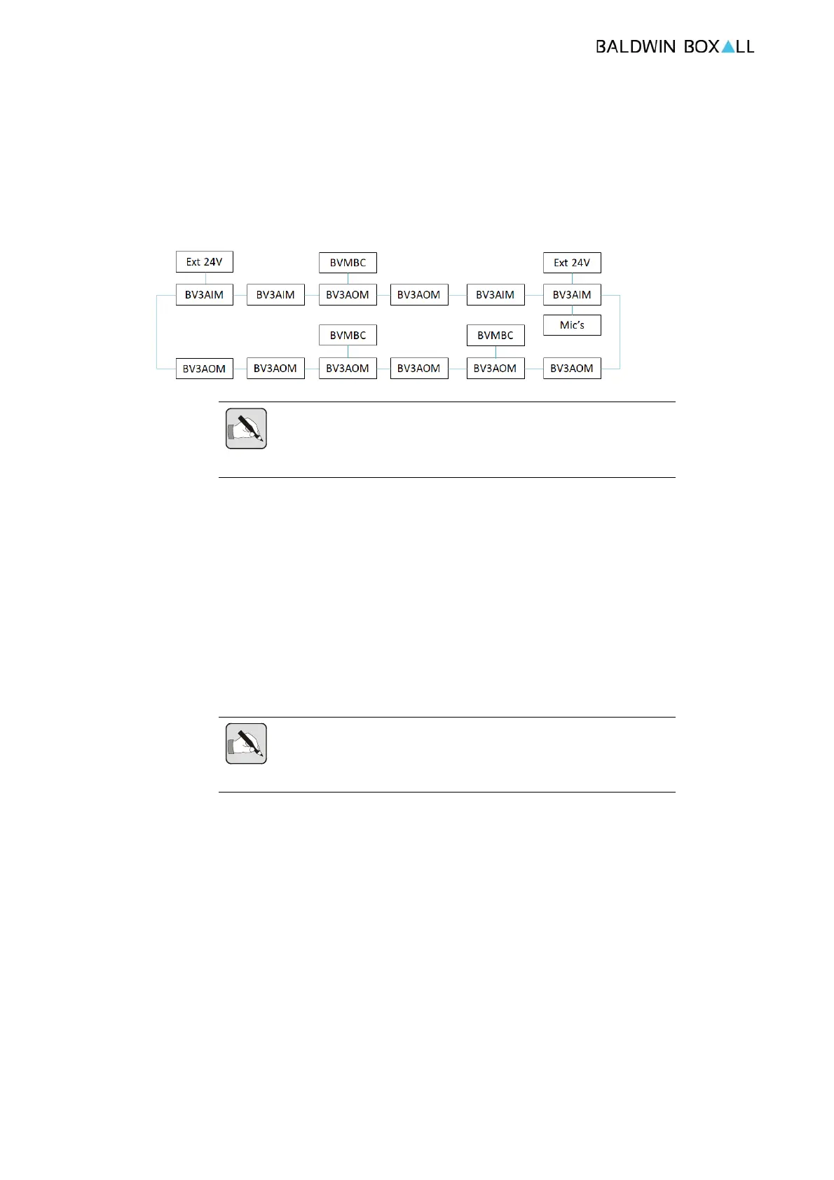
A device which is connected to Power Source can provide power
to up to 2 devices on each network connection therefore as a rule
of thumb there must be a power source connected as shown in the
diagram below;
Figure 2.2 — VIGIL3 Power Distribution
NOTE: If a BV3AOM8 is to have a VIGIL3 fan controller connected to it
via CAN Bus then this unit must also be connected to a BVMBC due to the
power demands of the fans.
2.10 REAL TIME CLOCK
The VIGIL3 system has a highly accurate RTC subsystem used for
Timed Cause and Effect rules and Time and Date stamping fault
logs hectic.
The time is maintained by all BV3A
OM8 modules and is set via
the VIGIL3 Configurator Application.
NOTE: The VIGIL3 system will maintain the time and date as long as it
is powered (either via mains or the backup batteries). If the system is
completely powered down the time and date will need to be set again.