VIGIL3 Voice Alarm
Overview, Architecture and Configuration
8 VIGIL3 Overview, Architecture & Configuration issue 2
2.3 AUDIO INPUT AND OUTPUT
N
UMBERING
VIGIL3 systems can be realised up to a maximum of 800 outputs
and 400 inputs. Input and output numbering is dependent on the
ID of the BV3AOM8 or BV3AIM2/4 module. The following
tables illustrate the input and output numbering conventions used
in a VIGIL3 system;
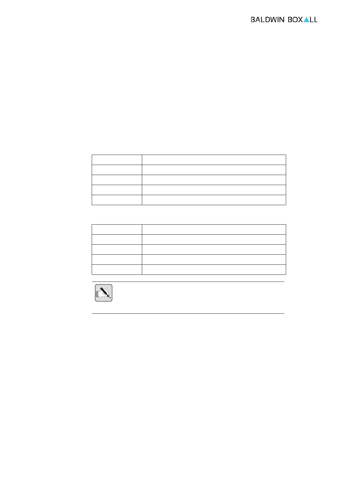
Table 2.1 — VIGIL3 Output Numbering
Unit ID Outputs
00 1-8
01 9-16
02 17-24
etc
Table 2.2 — VIGIL3 Input Numbering
Unit ID Inputs
00 1-4
01 5-8
02 9-12
etc
NOTE: VIGIL3 inputs are grouped in 4’s, if BV3AIM2 modules are used
some inputs will not be available e.g. BV3AIM2 (ID00) will have inputs
1&2 and BV3AIM2 (ID01) will have inputs 5&6
Please see the BV3AOM8 and BV3AIM2/4 installation manuals
for details of ID setting.
2.4 MICROPHONES
VIGIL3 supports both native VIGIL3 microphones (BVRDTSM)
and legacy Vigil 2 (BDM & BFM) microphones.
Each BV3AIM2/4 audio input has a cor
responding RS485 control
port which must be configured correctly (Protocol in use, BAUD
rates etc.)