BTL5-A11-M/U_ _ _ _-P-SA167-S 32
Micropulse Linear Transducer in Profile Housing
6
english
4 Wiring
Note the following when making
electrical connections:
System and control cabi-
net must be at the same
ground potential.
To ensure electromagnetic
compatibility (EMC), which Balluff
verifies by the CE Marking, the
following points must be strictly
observed.
BTL transducer and the proces-
sor/control must be connected
using shielded cable.
Shielding: Copper filament
braided, 80% coverage.
The shield must be tied to the
connector housing in the BKS
connector (
➥➥
➥➥
➥
Fig. 4-3); see in-
structions accompanying the con-
nector.
The cable shield must be
grounded on the control side, i.e.,
connected to the protection
ground.
Pin assignments can be found in
➥➥
➥➥
➥
Table 4-1. Connections on the
controller side may vary according
to the controller and configuration
used.
When routing the cable between the
transducer, controller and power
supply, avoid proximity to high volt-
age lines to prevent noise coupling.
Especially critical is inductive noise
caused by AC harmonics (e.g. from
phase-control devices), against
which the cable shield provides only
limited protection.
Cable length max. 20 m; Ø 6 to
8 mm. Longer lengths may be used
if construction, shielding and routing
are such that external noise fields
will have no effect on signal integrity.
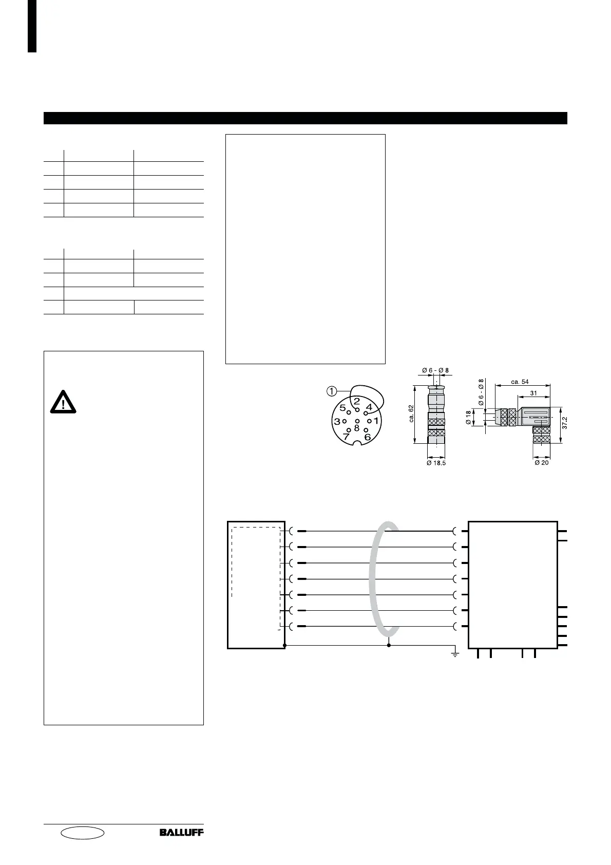
Fig. 4-1: Pin assignments BKS,
connector type BTL
BKS connector, view
towards solder side of
female BKS-S 32M-00
or BKS-S 33M-00
Table 4-1: Wiring assignment
straignt
BKS-S 32M-00
No. 99-5672-19-08
(Binder part no.)
right-angle
BKS-S 33M-00
No. 99-5672-78-08
Fig. 4-3: Connector (optional)
Cable entry
(PG 9 fitting)
➀ The analog transducer outputs
are potential-free. When connect-
ing to a module with non-poten-
tial-free inputs, ground loops may
cause erroneous signals. Avoid
this by defeating the potential-
free function in the transducer:
jumper Pin 2 and Pin 4 in the
female connector (Fig. 4-1).
➁ A small voltage difference
(< 10 mV) appears between pin 3
and 6 due to seperate output
drivers.
➂ Unused leads can be tied to
GND on the control side, but they
must never be connected to the
shield.
➃
Reference GND for supply
voltage and EMC!
Output signals
Pin Cable BTL5-A11
1 YE yellow not used
➂
2 GY grey 0 V
➀
3 PK pink 10...0 V
➁
6 GN green 0...10 V
➁
Supply voltage (external)
Pin Cable BTL5-A11
4 BU blue GND
➀ ➃
5 BN brown +24 V
7 not used
8 WH white GND
YE
GY
PK
BU
BN
GN
WH
not used
0 V
10...0 V
GND
+24 V
0...10 V
GND
BTL5-A11...-SA167-S 32
Fig. 4-2: BTL5-A11...SA167-S 32 with processor card/controller, wiring example
Processor/
controller with
analog input
1
2
3
4
5
6
8
 Loading...


