www.balluff.com 2
No. 873240 EN · I16; Subject to modification. Replaces K15.
english
Noise elimination
To avoid equipotential bonding - a current flow - through
the cable shield, please note the following:
– Use insulating bushes
– Put the control cabinet and the system in which the
transducer is located to the same ground potential.
Startup
DANGER
Uncontrolled system movement
When starting up, if the position measuring system is
part of a closed loop system whose parameters have not
yet been set, the system may perform uncontrolled
movements. This could result in personal injury and
equipment damage.
► Persons must keep away from the system's
hazardous zones.
► Startup must be performed only by trained technical
personnel.
► Observe the safety instructions of the equipment or
system manufacturer.
1. Check connections for tightness and correct polarity.
Replace damaged connections.
2. Turn on the system.
3. Check measured values and adjustable parameters
regularly (especially after replacing the transducer or
after repair by the manufacturer). Recalibrate the
transducer, if necessary.
The calibration procedure is described in the
comprehensive user's guide.
Operating notes
– Check the function of the transducer and all associated
components on a regular basis.
– Take the position measuring system out of operation
whenever there is a malfunction.
– Secure the system against unauthorized use.
Installing the transducer (continued)
The transducer is electrically isolated from the machine
with the supplied insulating bushes.
1. Guide the transducer into the mounting clamps.
2. Attach transducer to the base using mounting screws
(tighten screws in the clamps with max.2Nm).
3. Insert magnet (accessories).
Shielding and cable routing
Defined ground!
The transducer and the control cabinet must be
at the same ground potential.
Shielding
To ensure electromagnetic compatibility (EMC), observe
the following:
– Connect the transducer and controller using a shielded
cable.
Shielding: Copper filament braided, at least 85%
coverage.
– Shield is internally connected to connector housing.
Magnetic fields
The position measuring system is a magnetostrictive system.
It is important to maintain adequate distance between the
transducer and strong, external magnetic fields.
Cable routing
Do not route the cable between the transducer, controller,
and power supply near high voltage cables (inductive stray
noise is possible).
The cable must be routed tension-free.
Cable length
BTL7-A/G Max. 30 m1)
BTL7-C/E Max. 100 m1)
1) Prerequisite: Construction, shielding and routing preclude the effect of
any external noise fields.
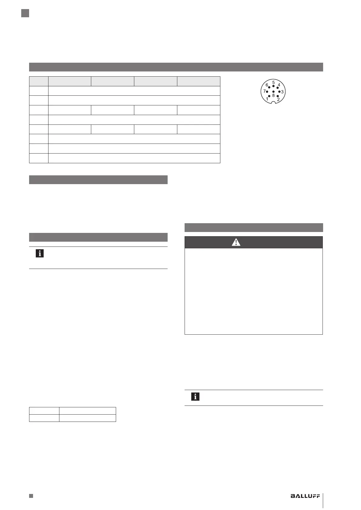
Electrical connection
Pin BTL7-A501-… BTL7-G501-… BTL7-C501-… BTL7-E501-…
Pin assignment of S115 connector (view of
connector pins of transducer)
1 0V (pin 3)
2 0V (pin 5)
3 10…0V1) 10…−10V1) 20…0mA1) 20…4mA1)
4 La (communication line)
5 0…10V1) −10…10V1) 0…20mA1) 4…20mA1)
1) Factory setting, can be freely configured with the
PC software.
2) Reference potential for supply voltage and
EMC-GND.
6 GND2)
7 10…30V
8 Lb (communication line)
BTL7-A/C/E/G501-M _ _ _ _ -P-S115
Micropulse Transducer in a Profile Housing
 Loading...


