1
Intended use
The BTL7 Micropulse Transducer, together with a machine
controller (e.g. PLC), comprises a position measuring
system. It is intended to be installed into a machine or
system and used in the industrial sector. Flawless function
in accordance with the specifications in the technical data
is ensured only when using original BALLUFF accessories.
Use of any other components will void the warranty.
Opening the transducer or non-approved use are not
permitted and will result in the loss of warranty and liability
claims against the manufacturer.
General safety notes
Installation and startup may only be performed by
trained specialists.
The operator is responsible for ensuring that local safety
regulations are observed. In particular, the operator must
take steps to ensure that a defect in the position
measuring system will not result in hazards to persons or
equipment.
If defects and unresolvable faults occur in the transducer, it
should be taken out of service and secured against
unauthorized use.
Downloading further instructions
A complete user's guide can be downloaded from the
Internet at www.balluff.com or requested via e-mail from
service@balluff.de.
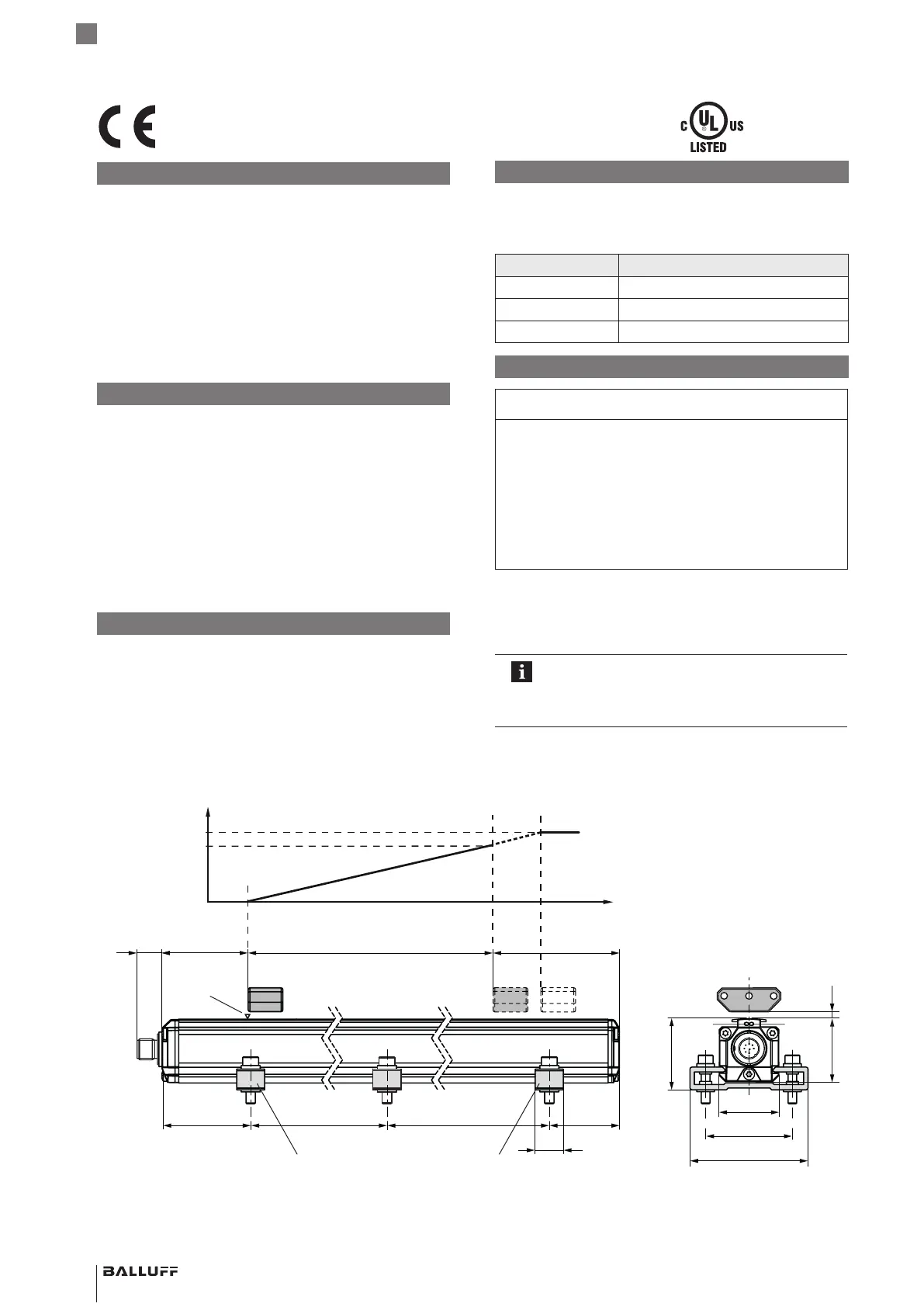
Dimensions and function
The transducer contains the waveguide. A magnet is
moved along the waveguide. This magnet defines the
position to be measured on the waveguide.
LED1/LED2 Operating state
Green Normal function
Red Error
Flashing green Programming mode
Installing the transducer
NOTICE!
Improper installation
Improper installation can compromise the function of the
transducer and result in damage.
► For this reason, ensure that no strong electrical or
magnetic fields are present in the immediate vicinity
of the transducer.
► The recommended spacing for the installation must
be strictly observed.
Any orientation is permitted. Mount the transducer on a
level surface of the machine using the provided mounting
clamps and cylinder-head screws. A sufficient number of
mounting clamps is supplied.
In order to avoid the development of resonant
frequencies from vibration loads, we
recommend arranging the mounting clamps at
irregular intervals.
english
BTL7-A/C/E/G501-M _ _ _ _ -P-S115
Micropulse Transducer in a Profile Housing
72 73
~80 ~80~250 ~250
15
50
35
68
41
36.8 ≤ 4
13.8
1) Unusable area
2) Not included in scope of
delivery
1)
Nominal length =
Measuring range
Null point End point
Output signal rising:
Error signal
100 %
0 %
BTL5-P-3800-2 magnet
1)
Mounting clamps with insulating bushes
and ISO4762M5x22 cylinder-head screws,
max. tightening torque 2Nm
2)
LED1
2)
LED2
The CE Mark verifies that our products
meet the requirements of the current
EMC Directive.
File no.
E227256
Groove
 Loading...


