Do you have a question about the Balluff BTL7-P511-M P-S32 Series and is the answer not in the manual?
| Category | Transducer |
|---|---|
| Protection Class | IP67 |
| Electrical Connection | M12 connector |
| Housing Material | Aluminum |
| Series | BTL7 |
| Type | Linear Position Transducer |
| Output Signal | Analog |
| Supply Voltage | 10 to 30 V DC |
| Temperature Range | -40 to +85 °C |
Describes the scope and applicability of the guide for the BTL7 Transducer.
Explains individual instructions, action sequences, and notes used in the manual.
Lists the items included with the BTL7 transducer, such as the transducer and mounting clamps.
Details regulatory approvals like UL and mentions relevant patents for the product.
Specifies that the transducer is for position measuring systems in machines, with original accessories.
Emphasizes installation by trained personnel and operator responsibility for safety.
Outlines the structure and meaning of signal words (NOTICE, DANGER) used for hazards.
Advises to observe national regulations for the proper disposal of the product.
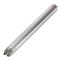
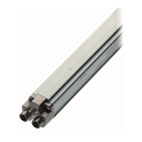
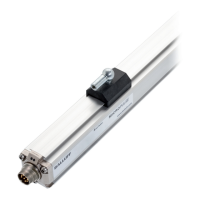
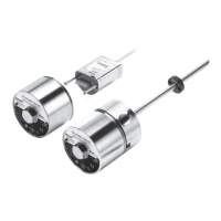
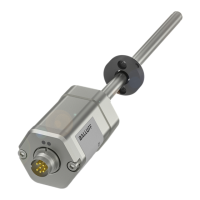
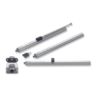
Describes the physical makeup, including housing, waveguide, connection, and magnet.
Explains how the transducer works using magnetic fields, ultrasonic waves, and time measurement.
Specifies the maximum number of magnets that can be used and the minimum distance between them.
Details the meaning of the status indicated by the two LEDs on the transducer.
Provides instructions on mounting the transducer securely and correctly, including clamp usage.
Gives guidelines for installing captive magnets, focusing on avoiding lateral forces and using joint rods.
Outlines installation requirements for floating magnets, including distances and offsets for accuracy.
Details how to connect the transducer, referencing pin assignments for different connector types.
Provides essential information on EMC compliance, cable management, and bending radii.
Guides users through the initial startup process, emphasizing safety precautions and checks.
Offers general advice for regular system checks, malfunction handling, and security.
Explains the P interface's function as a universal impulse interface for position control.
Describes the digital pulse interface and integrated protocol for data exchange and diagnostics.
Lists the typical accuracy specifications for the BTL7 transducer under various conditions.
Specifies the operating and storage temperature ranges, humidity, and shock/vibration resistance.
Details the required stabilized supply voltage, ripple limits, and overvoltage protection.
Describes the output signal characteristics, including start/stop difference and short-circuit protection.
Presents installation dimensions and details for captive magnet types like BTL5-M/N-2814-1S.
Shows installation dimensions and specifications for the joint rod accessory.
Provides conversion tables for millimeters to inches and inches to millimeters.
Illustrates the information found on the product's part label and explains its components.
