Do you have a question about the Balluff BTL6-E500-M Series and is the answer not in the manual?
The BTL6 Micropulse transducer is intended for use in a machine or system, with a controller (PLC), for position measurement.
This guide is for specialized personnel performing installation and setup of the system.
Relevant safety regulations must be followed; ensure transducer system defects do not cause hazards.
This guide applies to the BTL6-E...E2/E28-KA/KE/LA... Micropulse transducer. See section 6 for model overview.
Describes the transducer's operation using a waveguide, magnet, and magnetostrictive torsional wave for position measurement.
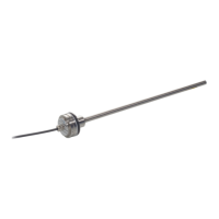
Dimensional drawing and specifications for the '-KA' axial, centric installation type of the transducer.
Dimensional drawing and specifications for the '-KE' axial, eccentric installation type of the transducer.
Dimensional drawing and specifications for the '-LA' axial installation type with leads.
Important notes on avoiding strong electrical/magnetic fields and supporting horizontal mounting for long stroke lengths.
Details on permissible distances, mounting in a toleranced hole using O-ring/support ring, and fixing with M5 threaded studs.
Guidance on ordering and mounting the magnet, recommending non-magnetizable material for mounting.
Notes on electrical connections, EMC, shielded cable usage, and grounding for proper system operation.
Verify connections carefully before applying power to prevent damage from improper connections or overvoltage.
Note potential uncontrolled movements on initial startup or in closed-loop systems with unset parameters; ensure safety.
Advise verifying start/end position values after replacement/repair, and making corrections if deviations are found.
The system's functionality and associated components should be regularly checked and recorded.
If the system operates improperly, take it out of service and guard against unauthorized use.
Recommend grounding the control cabinet and system to the same potential to avoid equipotential bonding current flow through the cable shield.
Lists items included in the transducer shipment: transducer with guide, O-ring, and support ring.
Details available stroke lengths (50-1500 mm for E2, 50-1016 mm for E28) and magnet compatibility.
Information on magnets available for order, including part numbers, dimensions, weight, housing, and operating temperature.
Refers to page 4 for dimensions, provides weight (approx. 2.0 kg/m), housing material, pressure tube, E-Modulus, and operating/storage temperatures.
Specifies supply voltage as DC 10-30 V, with ripple < 0.2 Vss and typical current draw 2 W.
Defines output signals: 4-20 mA position signal and < 4 mA error signal (typ. 3.6 mA).
Details overvoltage protection: dielectric strength 500 V DC, overvoltage 36 V, and polarity reversal protection max. 40 V.
Confirms product compliance with EMC Directive 89/336/EEC and lists relevant standards.
| Series | BTL6-E500-M |
|---|---|
| Type | Magnetostrictive Linear Position Transducer |
| Operating Voltage | 10...30 VDC |
| Protection Class | IP67 |
| Output Signal | Analog |
| Linearity | ±0.02% F.S. |
| Connection | M12 connector |
| Measuring Length | 500 mm |