Do you have a question about the Balluff BTL5-P and is the answer not in the manual?
Transducer intended for machine/system position measurement with controller/processor.
Guide intended for specialized personnel for installation and setup.
Follow safety regulations; ensure no hazards from defects; install safety switches.
High resolution, repeatability, linearity, bus-interface, shock/vibration immunity, absolute signal, long cable lengths, IP 67.
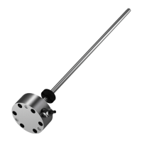
Transducer uses waveguide, magnet, and magnetostrictive wave for position measurement.
Ensure no strong fields; mount using brackets; use isolation bushings.
Magnet attached to moving member; must be on a track parallel to transducer; provides spacing/offset figures.
Lateral forces to be avoided; connections must permit freedom of movement; assumes connection via rod.
Wiring for RS485 differential supply (24V, ±15V) showing pin assignments.
Wiring for Single-ended supply (24V, ±15V) showing pin assignments.
Example wiring diagram for BTL5-P1...KA__ with a processor controller.
Check connections carefully before applying power due to polarity reversal protection and overvoltage.
If system operates improperly, take it out of service and guard against unauthorized use.
Avoid potential differences in cable shield current flow; use isolation bushings and ensure common ground.
Specifications for regulated supply voltage, ripple, current draw, and protection features.
Details on INIT pulse level, RS485 driver length, and pulse length warnings.
Information on shielded cable type, length, and diameter for processor connection.
| Protection Class | IP67 |
|---|---|
| Type | Magnetostrictive |
| Output Signal | Analog |
| Analog output | 0...10 V, 4...20 mA |
| Operating voltage Ub | 10...30 VDC |
| Supply Voltage | 10...30 VDC |
| Operating Temperature | -40...85 °C |
| Connection Type | Connector |