1-800-543-8390 • WWW.BALLUFF.COM
BTL5-P/I/K/L/M_-M/U_ _ _ _-P-S32/KA_ _
Micropulse Linear Transducer
Digital Output / Profile Housing
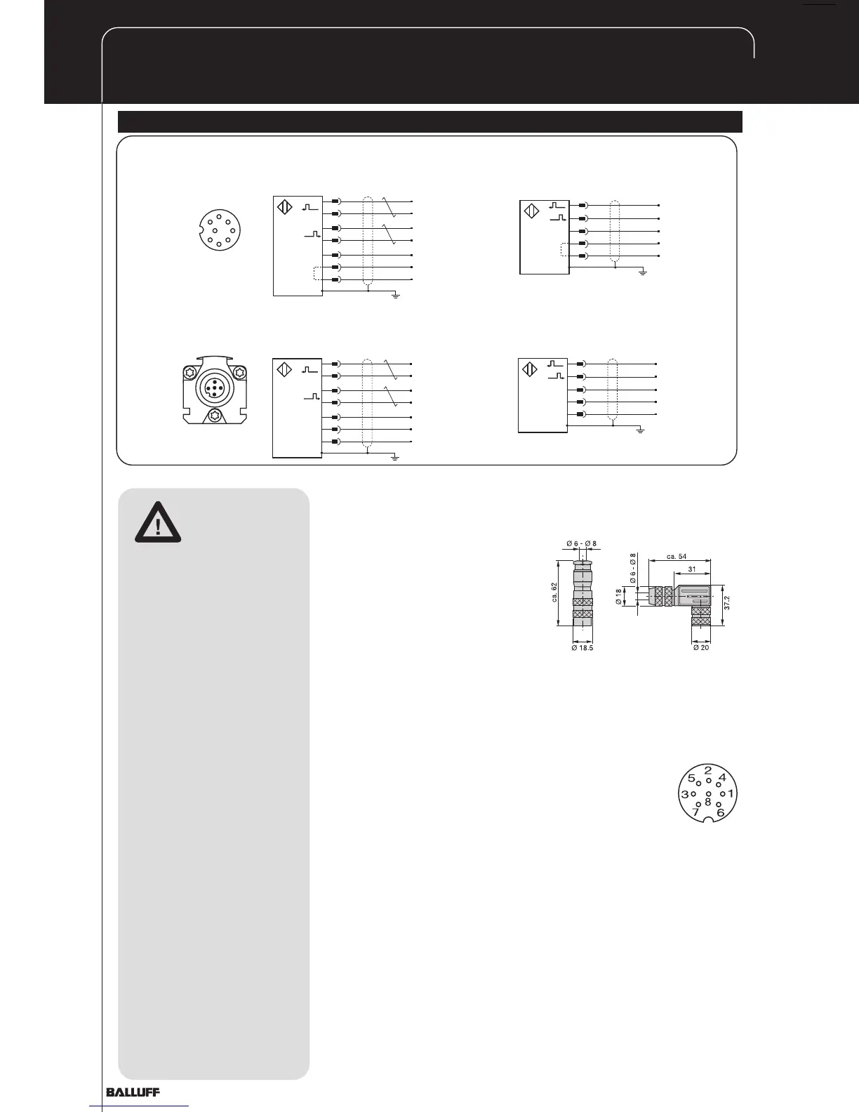
4 Wiring
straignt
BKS-S 32M-00
right-angle
BKS-S 33M-00
Cable entry
(PG 9 fitting)
Note the following
when making
electrical connec-
tions:
System and control cabinet
must be at the same
ground potential.
To ensure the electromagnetic
compatibility (EMC) which
Balluff warrants with the CE
Mark, the following instruc-
tions must be strictly
followed.
BTL transducer and the
processor/control must be
connected using
shielded cable.
Shielding: Copper filament
braided, 80% coverage.
The shield must be tied to the
connector housing in the
BKS connector (Fig. 4-1); see
instructions accompanying
the connector.
In the cable version the cable
shield is connected to the
housing in the PG fitting.
The cable shield must be
grounded on the control side,
i.e., connected to the
protection ground.
Pin assignments can be
found in Table 4-1. Connec-
tions on the controller side
may vary according to the
controller and configuration
used.
When routing the cable between
the transducer, controller and
power supply, avoid proximity to
high voltage lines to prevent noise
coupling.
Especially critical is inductive
noise caused by AC harmonics
(e.g. from phase-control devices),
against which the cable shield
provides only limited protection.
Cable length max. 500 m ;
Ø 6 to 8 mm.
High noise immunity on the line
between the transducer and
processor is provided by the
differential line drivers used for
the RS 485/422 interface. The
differential signal is carried to the
processor, which makes it
available as analog or digital
information for
further processing.
Fig. 4-1: Connector (optional)
1YE
3PK
Interrogate + Input
Interrogate - Input
2GY
5GN
Pulse + Output
Pulse - Output
7BN
6BU
+24 V
GND
Digital, RS485 differential
24 V (P, M, I, K, L, R)
8WH
GND
0117a025
1
2
3
4
5
6
7
8
View of mating
connector, wiring side
1YE
Interrogate + Input
2GY
Pulse + Output
7BN
6BU
+24 V
GND
Digital, Single-ended
24 V (N)
8WH
GND
0117a026
1YE
3PK
Interrogate + Input
Interrogate - Input
2GY
5GN
Pulse + Output
Pulse - Output
7BN
6BU
+15 V
GND
Digital, RS485 differential
±15 V (P, M, I, K, L, R)
8WH
-15 V
0117a027
1YE
Interrogate + Input
2GY
Pulse + Output
7BN
6BU
+15 V
GND
Digital, Single-ended
±15 V (N)
8WH
- 15 V
0117a028
Fig. 4-2: Pin assignments BKS,
connector type BTL
BKS connector,
view towards
solder side of
female BKS-S
32M-00 or BKS-S
33M-00