WWW.BALLUFF.COM • 1-800-543-8390
BTL5-P/I/K/L/M_-M/U_ _ _ _-P-S32/KA_ _
Micropulse Linear Transducer
Digital Output / Profile Housing
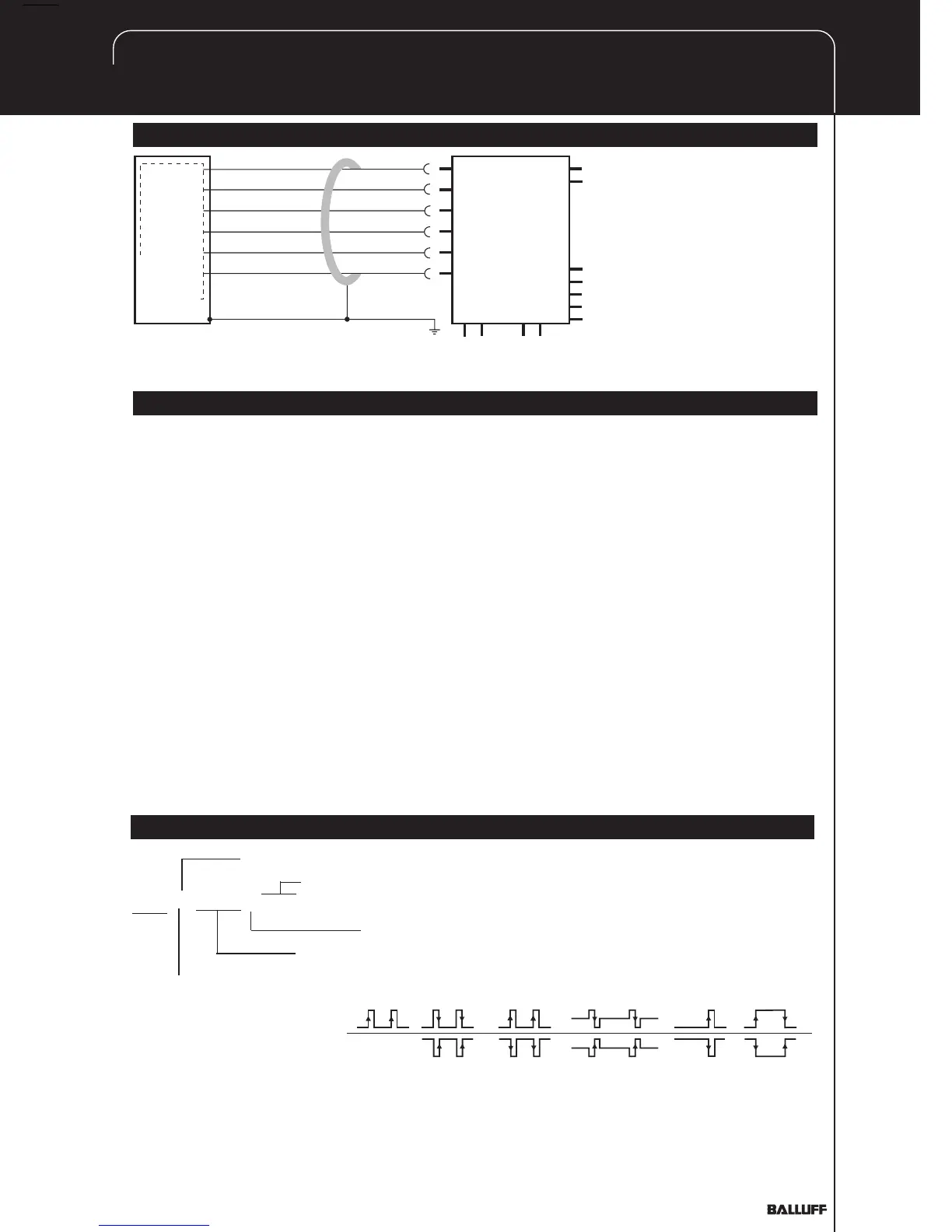
4 Wiring (cont.)
INIT
START/STOP
INIT
START/STOP
GND
+24 V
YE
GY
PK
GN
BU
BN
BTL5-P1...KA_ _
processor or
controller
Fig. 4-3: BTL5-P1...KA_ _ with processor controller, wiring example
5 Startup
5.1 Check connections
Although the connections are
polarity reversal protected,
components can be damaged
by improper connections and
overvoltage. Before you apply
power, check the connec-
tions carefully.
5.2 Turning on the system
Note that the system may
execute uncontrolled move-
ments when first turned on or
when the transducer is part of a
closed-loop system whose
parameters have not yet been
set. Therefore make sure that
no hazards could result from
these situations.
5.3 Check output values
After replacing or repairing a
transducer, it is advisable to verify
the values for the start and end
position of the magnet in manual
mode. If values other* than those
present before the replacement or
repair are found, a correction should
be made.
* Transducers are subject to
modification or manufacturing
tolerances.
5.4 Check functionality
The functionality of the transducer
system and all its associated
components should be regularly
checked and recorded.
5.5 Fault conditions
When there is evidence that the
transducer system is not
operating properly, it should be
taken out of service and
guarded against unauthor-
ized use.
5.6 Noise elimination
Any difference in potential -
current flow - through the cable
shield should be avoided.
Therefore:
– Use the isolation bushings,
and
– Make sure the control
cabinet and the system in
which the BTL5 is contained
are at the same
ground potential.
Micropulse
Linear Transducer
6 Versions (indicated on part label)
Supply voltage 1 = DC 24 V, 2 = DC ±15 V
Electr. connect., S32: with connector,
BTL5-P1-M0450-P-S32 KA05: with 5 m cable
Profile form factor
Nominal stroke (4 digits): M = Metric units [mm]
U = Inch units [1/10 in.]
Digital output signals: BTL5-N... BTL5-P... BTL5-M... BTL5-I... BTL5-K... BTL5-L...
Start Stop Start Stop Start Stop Start Stop Stop Gate
(Trailing Edge
Active)
(Leading Edge
Active)
(RS-485
Multiplex)
(Leading Edge
Active)
(Pulse-width-
Modulated)
Single Ended