1-800-543-8390 • WWW.BALLUFF.COM
BTL5-P/I/K/L/M_-M/U_ _ _ _-P-S32/KA_ _
Micropulse Linear Transducer
Digital Output / Profile Housing
3 Installation (cont.)
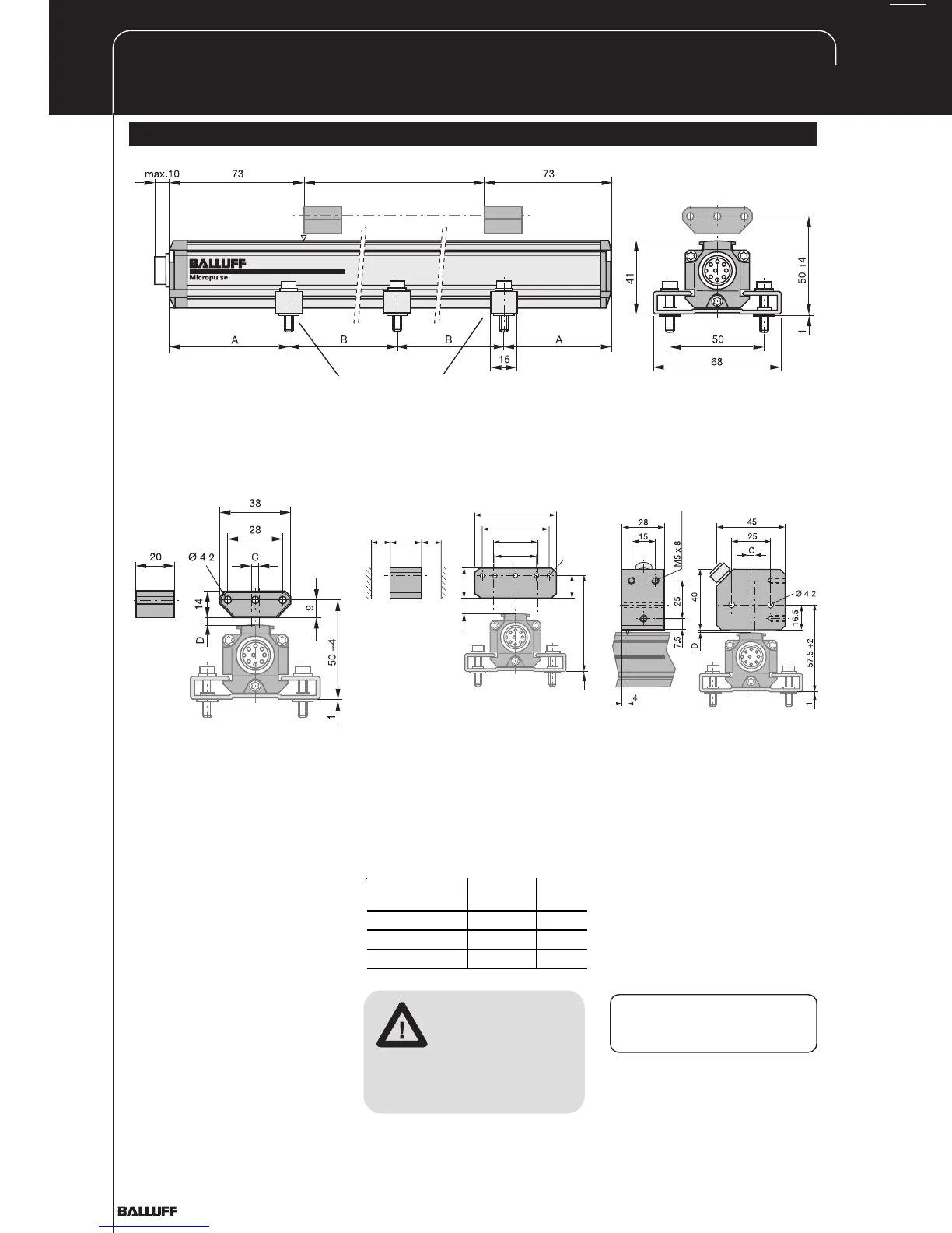
Fig. 3-1: Dimensional drawing (BTL5...P-S 32 transducer with floating magnet BTL5-P-3800-2)
NL
Nominal stroke
Mounting brackets with isolation bushings and M5 x 22
cylinder head screws, DIN 912, max. tightening torque 2
Nm
55
28
45
21
Ø 4.2
20
61 +10
1
15
E
E
C
D
Fig. 3-2: BTL5-P-3800-2 magnet Fig. 3-4: BTL5-P-4500-1
electromagnet (24 V/100 mA)
Fig. 3-3: BTL5-P-5500-2 magnet
max. permissible
tightening torque 2 Nm
3.2 Floating magnets
The floating magnet (Figs. 3-2
to 3-4) is attached to the
moving member of the machine
using non-magnetizable screws
(brass, aluminum). To ensure
the accuracy of the transducer
system, the moving member
must carry the magnet on a
track parallel to the transducer.
The following table provides
figures in [mm] for the spacing
which must be maintained
between magnet and transducer
and for the permissible center
offset:
Magnet type Distance
" D "
Offset
" C "
BTL5-P-3800-2 0.1 ... 4 ± 2
BTL5-P-5500-2 5 ... 15 ± 15
BTL5-P-4500-1 0.1 ... 2 ± 2
BTL5-P-4500-1 magnet,
special features: Multiple
magnets on the same
transducer can be turned on
and off individually (PLC control
signal).
The stroke range is offset 4
mm towards the BTL
connector/cable (Fig. 3-4).
Ensure that the
distance E between
parts made of
magnetizable
material and the
BTL5-P-5500-2 magnet is at
least 12 mm (Fig. 3-3).