WWW.BALLUFF.COM • 1-800-543-8390
BTL5-P/I/K/L/M_-M/U_ _ _ _-P-S32/KA_ _
Micropulse Linear Transducer
Digital Output / Profile Housing
3 Installation (cont.)
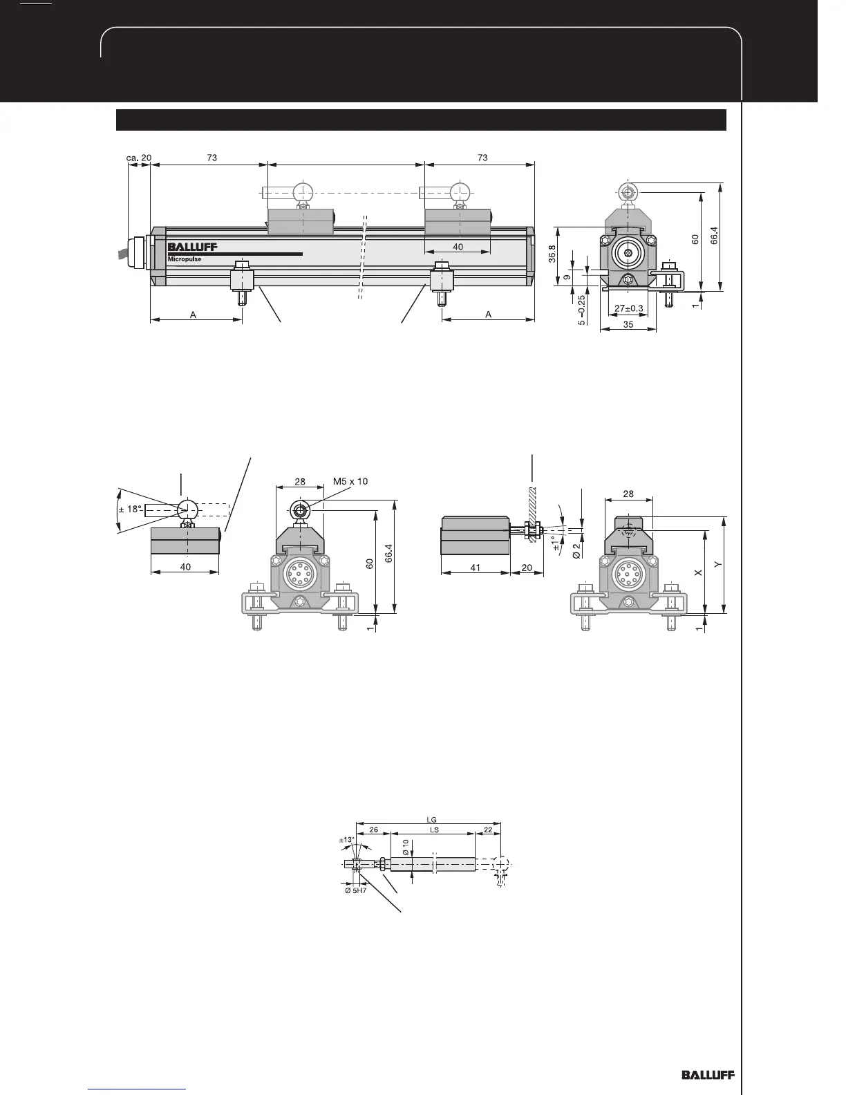
Fig. 3-5: Dimensional drawing (BTL5...P-KA transducer with captive magnet BTL5-F-2814-1S)
Mounting brackets with isolation bushings and M5 x 22
cylinder head screws, DIN 912,
max. tightening torque 2 Nm
Black,
round
marking
NL
Nominal stroke
Ball joint "B"
DIN 71805,
rotates horizontally
Black, round
marking
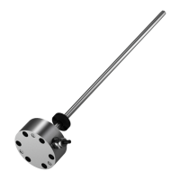
Fig. 3-6: BTL5-F-2814-1S magnet
Fig. 3-7: BTL5-M/N-2814-1S magnet
Mechanically joined to M5
stud using 2 nuts
Max. angle offset
Max. parallel offset
BTL5-M-2814-1S: X = 48.5 Y = 57
BTL5-N-2814-1S: X = 51 Y = 59.5
3.3 Captive magnets
Lateral forces are to be avoided
when using captive magnets
(Figs. 3-6 and 3-7). Connections
are required here which permit the
corresponding degree of freedom
with respect to the direction of
movement of the magnet along
the stroke range. It is assumed
that the BTL5-F-2814-1S magnet
is connected to the machine
member using a connecting rod.
The BTL2-GS08...A connecting
rod (Fig. 3-8) is available as an
accessory (please indicate length
LS when ordering).
Jam nut DIN 934 M5
Swivel eye DIN 648
Ball joint "B" DIN 71805,
rotates horizontally (part of
BTL5-F-2814-1S) magnet)
Fig. 3-8: BTL2-GS08-_ _ _ _-A
connecting rod