BTL6-E500-M_ _ _ _-E2/E28-KA_ _/KE_ _/LA_ _
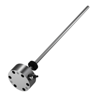
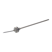
Micropulse Transducer - Rod Style
english
2
Read this manual before installing
and operating the Micropulse
Transducer.
1.1 Proper application
The BTL6 Micropulse transducer is
intended to be installed in a ma-
chine or system. Together with a
controller (PLC) it comprises a posi-
tion measuring system and may
only be used for this purpose.
Unauthorized modifications and
non-permitted usage will result in
the loss of warranty and liability
claims.
1.2 Qualified personnel
This guide is intended for special-
ized personnel who will perform the
installation and setup of the system.
1.3 Use and inspection
The relevant safety regulations must
be followed when using the trans-
ducer system. In particular, steps
must be taken to ensure that should
the transducer system become de-
fective no hazards to persons or
property can result.
1 Safety Advisory
1.4 Scope
This guide applies to the model
BTL6-E...E2/E28-KA/KE/LA...
Micropulse transducer.
An overview of the various models
can be found in
➥ ➥
➥ ➥
➥ section 6 Ver-
sions (indicated on part label) on
page 7.
Note: For special versions,
which are indicated by an
-SA_ _ _ designation in the part
number, other technical data
may apply (affecting calibration,
wiring, dimensions etc.).
Contents
1 Safety Advisory .................... 2
1.1 Proper application ................. 2
1.2 Qualified personnel ............... 2
1.3 Use and inspection ............... 2
1.4 Scope ..................................... 2
2 Function and
Characteristics ..................... 3
2.1 Function ................................. 3
3 Installation ............................ 4
3.1 Installation variants ............... 5
3.2 Transducer, Installation ......... 5
3.3 Magnets, Installation ............. 6
4 Wiring .................................... 6
5 Startup .................................. 7
5.1 Check connections ................ 7
5.2 Turning on the system ........... 7
5.3 Check output values ............. 7
5.4 Check functionality ................ 7
5.5 Fault conditions ..................... 7
5.6 Noise elimination ................... 7
6 Versions (indicated on
part label) .............................. 7
6.1 Included in shipment ............. 7
6.2 Available stroke lengths
and magnets .......................... 7
7 Accessories (order
separately) ............................ 7
7.1 Magnets ................................. 7
8 Technical Data ...................... 8
8.1 Dimensions, weights,
ambient conditions ................ 8
8.2 Supply voltage (external) ....... 8
8.3 Output signals ....................... 8
8.4 Overvoltage protection .......... 8
 Loading...