BTL6-E500-M_ _ _ _-E2/E28-KA_ _/KE_ _/LA_ _
Micropulse Transducer - Rod Style
5
english
3 Installation (cont.)
3.1 Installation variants
Be sure that no strong
electrical or magnetic
fields are generated in the
direct vicinity of the transducer.
For horizontal mounting of trans-
ducer with stroke lengths greater
than 500 mm, the pressure tube
should be supported or attached
at its end.
Be sure that no strong electrical or
magnetic fields are generated in
the direct vicinity of the
transducer.
➥➥
➥➥
➥ Fig. 3-3.
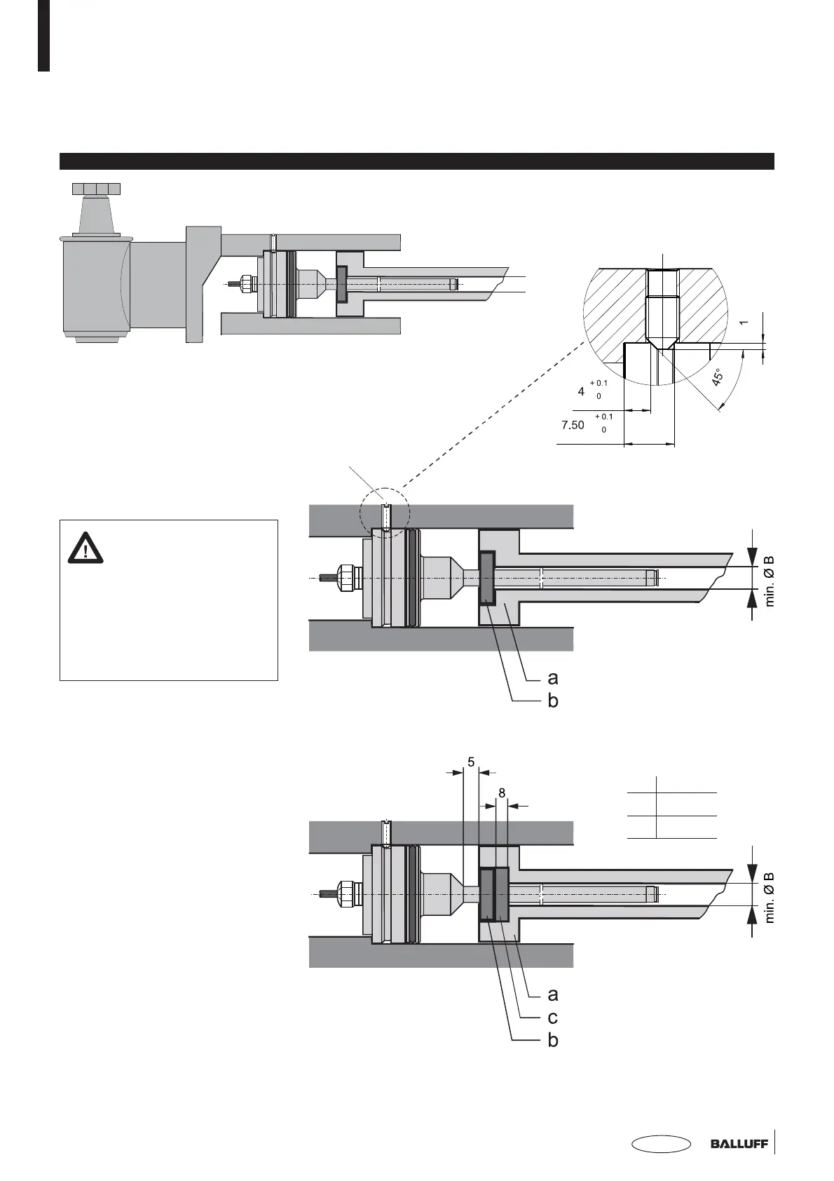
3.2 Transducer, Installation
The smallest permissible distance
between magnet ring and rod
mounting surface is shown in
Fig. 3-1.
Essentially the BTL transducer can
be attached in two ways in a
toleranced hole – Ø 48 H8 –,
whereby sealing is accomplished
using the O-ring and support ring
supplied:
The body of the transducer is
fixed in place using 3 M5 threaded
studs at 120° spacing.
Threaded stud M5
a = magnetizable material
b = magnet
c = spacer of non-
magnetizable material
a = non-magnetizable material
b = magnet
Fig. 3-2: Micropulse Transducer BTL6-E500....E2/E28..., installation
Threaded stud DIN 914 M5x8
B
E2 13 mm
E28 11 mm
Fig. 3-4: Installation: at magnetizable material
Fig. 3-3: Installation: at non-magnetizable material
 Loading...