14 english
6
P interface
6.1 Principle
The P interface is a universal impulse interface and unifies
the functions of the falling and rising edges. The position
measuring system control is done via Init and start/stop
signals. Here, the “start pulse” is the reference point for the
travel time measurement.
Reliable signal transmission, even with cable lengths of up
to 500m between the evaluation unit and transducer is
ensured by the particularly fail-safe RS485 differential driver
and receiver. Interfering signals are effectively suppressed.
DPI/IP is a protocol for direct data exchange between the
controller and transducer. Here, the signal lines transmit
additional information, such as manufacturer, sensor type,
measuring length, and waveguide velocity. This makes it
possible to start up or exchange a transducer without
needing to manually change the control parameters.
The interface enables bi-directional communication and
includes integrated diagnostic functions. Downtimes are
reduced thanks to Plug&Play and automatic
parameterization.
6.2 DPI/IP method
6.2.1 Function and characteristics
The DPI/IP method includes two operating modes, DPI
measuring operation and operation with the IP data protocol.
DPI = digital pulse interface
IP = integrated protocol
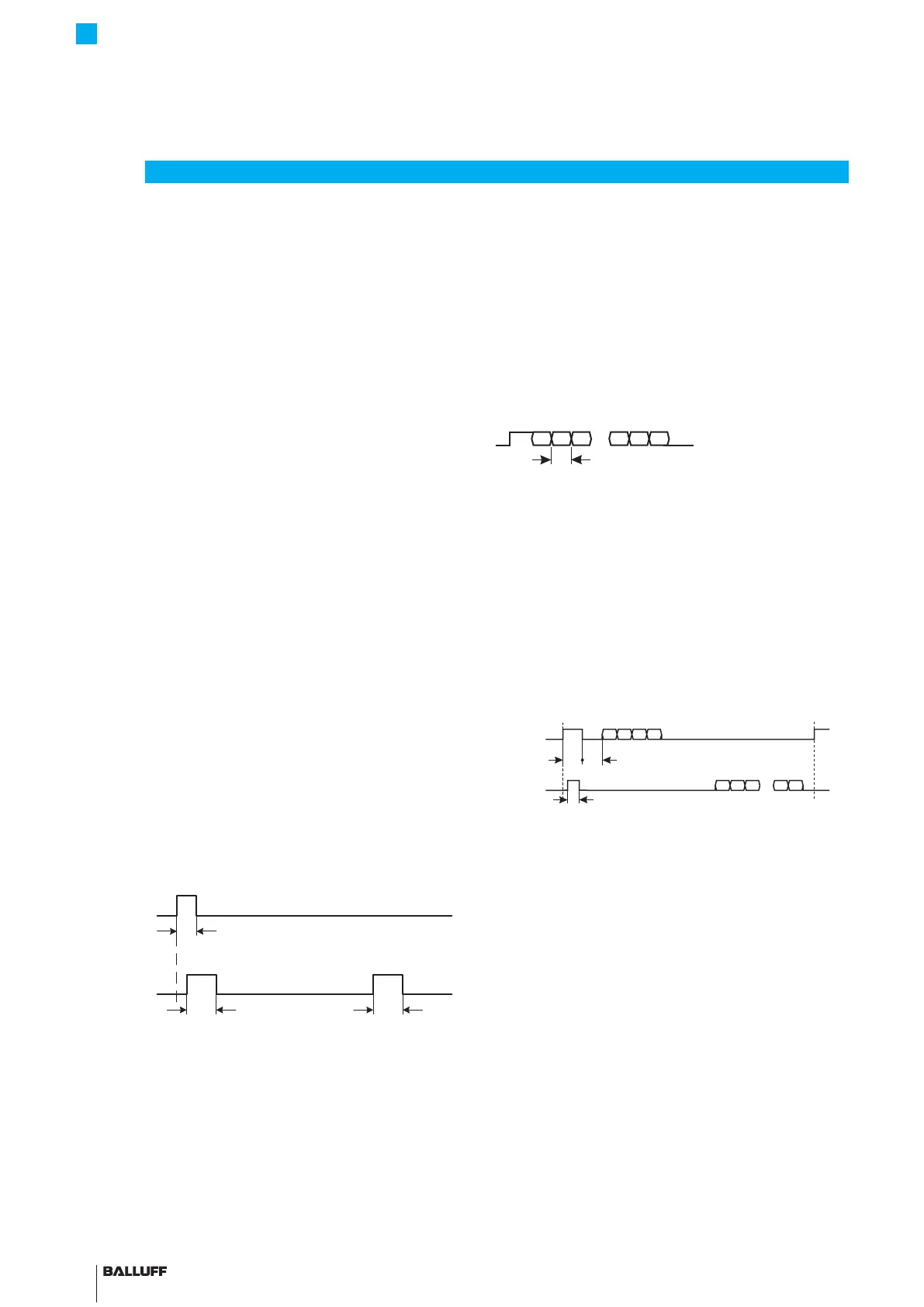
DPI measuring operation
The Init pulse is sent to the transducer via the Init line at
regular intervals, its rising edge triggers a measurement.
Fig. 6-1:
T
Init
T
T
Init
Start/Stop
Principle of data transfer in DPI measuring operation
T
Init
1μs to5μs
T
Start
3μs to 5μs (typ. 4µs)
T
Stop
3μs to 5μs (typ. 4µs)
Operation with IP data protocol
If the length of the Init pulse T
IP
is extended to 10μs to
50μs, the transducer switches from DPI measuring mode
to operation with the IP data protocol (see Fig. 6-2).
Here, a character string (command) is transferred to the
transducer after the Init pulse. While the start pulse is still
sent by the transducer as a response on the start/stop
line, a character string (response) is transferred to the
controller instead of the stop pulses, which contains the
requested response dependent on the command.
Each character in the transfer protocol has the following
bitstructure:
Start Bit0 Bit1 Bit2 Bit6 Bit7 PBit Stop
T
Start bit Start-of-frame bit
Bit 0 to bit7 8 data bits
PBit Parity bit (even parity)
Stop Stop-of-frame bit
T
Bit
4 μs (bit length at a data rate of 250 kbit/s)
Data security during transfer of the string is achieved with
the parity and CRC16 checks with polynomial
X16+X12+X5+1 (corresponds to 0x1021). If there is a
transfer or protocol error, the transducer sends an
appropriate error message as the response.
Fig. 6-2:
T
D1
Response
T
IP
T
Init
p
…
Principle of data transfer with the IP data protocol
T
IP
10 μs to50μs
Operation with IP data protocol
Command Command to request transducer data
(information that is stored in the transducer)
T
Start
3μs to 5μs (typ. 4µs)
T
D1
>50μs
Response Response in line with the request
Alternative: error message
BTL7-P511 -M ____ -P-S32/S115/KA_ _
Micropulse Transducer in a Profile Housing

 Loading...


