Do you have a question about the Balluff BTL6-A/C/E/G500-M Series and is the answer not in the manual?
Specifies the product versions and scope of the guide.
Explains symbols and conventions used in the manual for clarity.
Lists the items included with the BTL6 transducer.
Details certifications, compliance marks, and standards met by the product.
Defines the intended application of the position measuring system and restrictions.
Safety guidelines for installation, operation, and personnel qualifications.
Explains signal words and structure of hazard warnings.
Instructions for proper disposal of the product according to regulations.
Details on housing, electrical connection, and magnet types.
Explanation of the magnet-driven torsional wave principle and signal generation.
Describes the meaning of the LED indicator for operating states.
Guidance on mounting the transducer, avoiding improper installation and ensuring correct setup.
Instructions for installing captive magnets, avoiding lateral forces and using joint rods.
Guidelines for floating magnet installation, distances, and offsets.
Details pin assignments for S115 connectors and wiring.
Recommendations for ensuring EMC compatibility and proper cable management.
Procedure for system startup, including safety warnings and checks.
Regular checks and procedures for safe operation and shutdown.
Explanation of programming inputs La and Lb and the use of the adjusting box.
Prerequisites for calibration and notes on setting null and end points.
Overview of teach-in, inverting, and reset procedures.
Detailed steps for performing the teach-in process for setting null and end points.
Steps to invert the output gradient, including activation and abortion.
Procedure for resetting the transducer to factory settings.
Specifications for transducer accuracy, resolution, and repeat accuracy.
Operating and storage temperature, humidity, and shock/vibration ratings.
Details on voltage, ripple, current draw, and protection features.
Output types, voltage/current ranges, load resistance, and short circuit protection.
Information on programming inputs and overvoltage protection.
Physical dimensions, housing height, and weight.
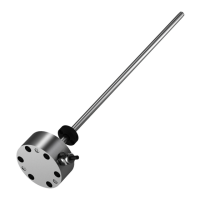
Installation dimensions and details for captive magnet types.
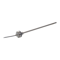
Details and installation information for the joint rod accessory.
Installation dimensions for various floating magnet types.
Information on connector types, pin assignments, and cable lengths.
Details on the adjusting box accessory and its scope of delivery.
Explains the structure and meaning of the product's type code.
Conversion tables for millimeters to inches and vice versa.
Explanation of the information found on the product's part label.
| Brand | Balluff |
|---|---|
| Model | BTL6-A/C/E/G500-M Series |
| Category | Transducer |
| Language | English |