www.balluff.com 7english
3.1 Construction
Electrical connection: The electrical connection is made
via a connector (see ordering code on page 20).
Housing: Aluminum housing containing the waveguide
and processing electronics.
Magnet: Defines the position to be measured on the
waveguide. Magnets are available in various models and
must be ordered separately (see accessories on page18).
Nominal length: To optimally adapt the transducer to the
application, the following nominal lengths are available:
Nominal length Grading
50…4572mm 5mm
3.2 Function
The BTL6 transducer contains the waveguide which is
protected by an aluminum housing. A magnet is moved
along the waveguide. This magnet is connected to the
system part whose position is to be determined.
The magnet defines the position to be measured on the
waveguide.
An internally generated INIT pulse interacts with the
magnetic field of the magnet to generate a torsional wave
in the waveguide which propagates at ultrasonic speed.
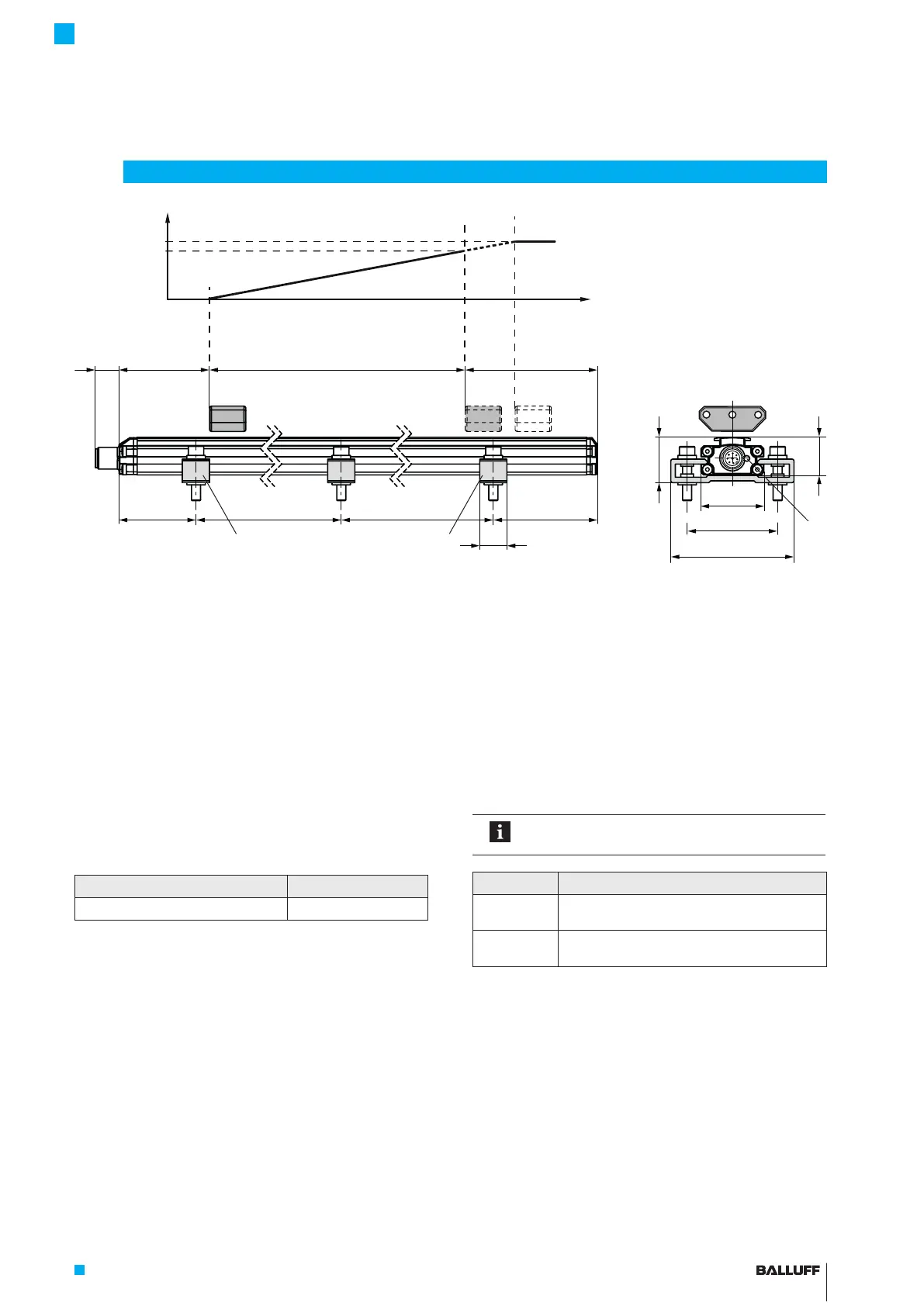
Fig.3-1: BTL6... transducer, construction
The component of the torsional wave which arrives at the
end of the waveguide is absorbed in the damping zone to
prevent reflection. The component of the torsional wave
which arrives at the beginning of the waveguide is conver-
ted by a coil into an electrical signal. The travel time of the
wave is used to calculate the position. Depending on the
version, this information is made available as a voltage or
current output with a rising gradient.
3.3 LED display
In normal operation the LED indicates the
operating states of the transducer.
LED Operating state
Green Normal function
Magnet is within the limits.
Red Error
No magnet or magnet outside the limits.
3
Construction and function
13 73 73
~80 ~80~250 ~250
15
50
34.8
68
24.8
20.8
1) Unusable area
2) Not included in scope
of delivery
1)
Nominal length =
Measuring range
Null point End point
Output signal rising:
Error signal
100 %
0 %
BTL5-P-3800-2 magnet
1)
Mounting clamps with insulating bushes
and ISO4762M5x25 cylinder-head screws,
max. tightening torque 2Nm
2)
LED
2)
BTL6-A/C/E/G500-M _ _ _ _ -PF-S115
Micropulse Transducer in a Flat Profile Housing

 Loading...