10 english
4.4 Electrical connection
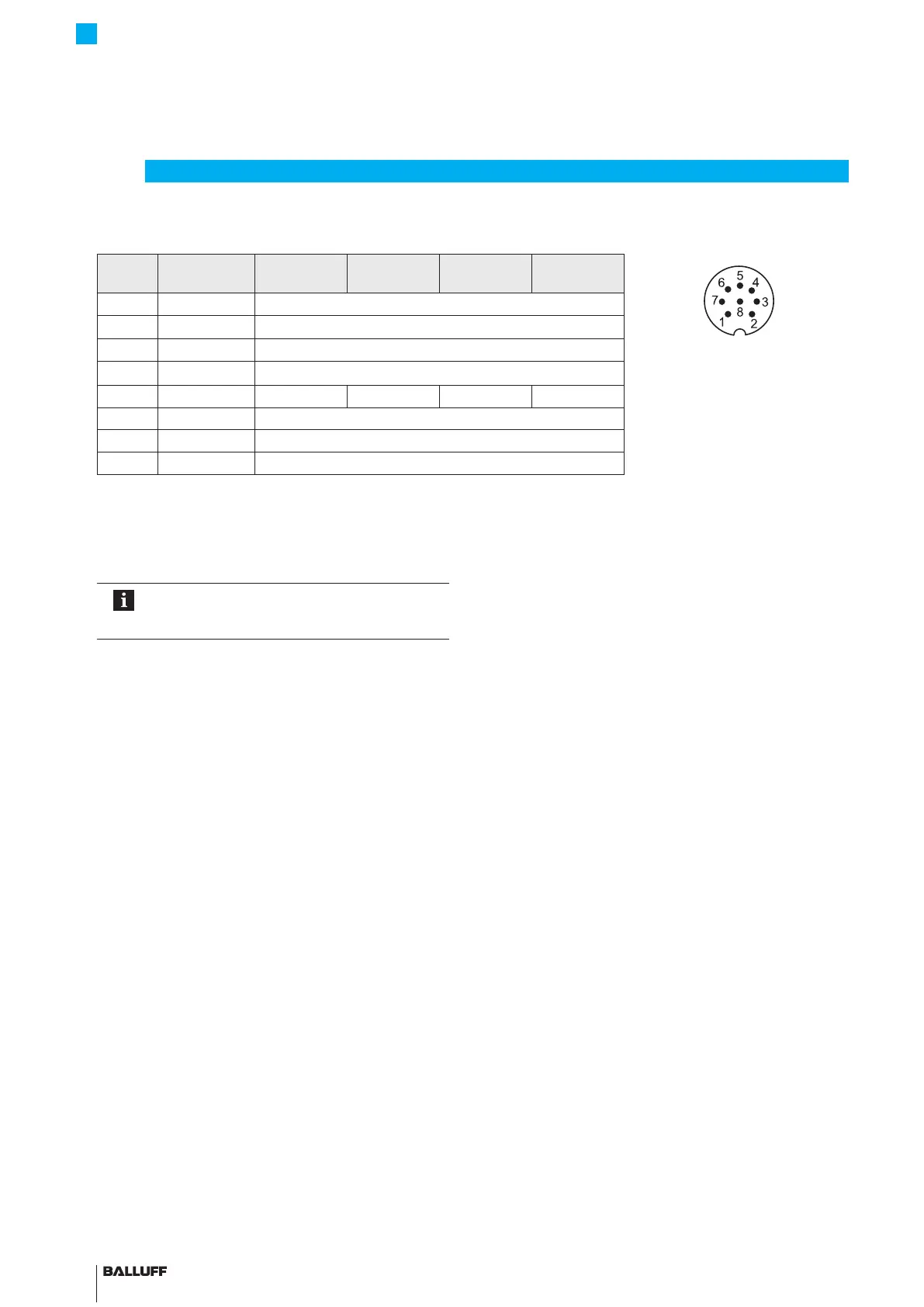
Pin BKS-S115-...
BKS-S116-...
-A500 -G500 -C500 -E500
Fig.4-8: Pin assignment of S115
connector (view of connector
pins of transducer)
1 Yellow Not used
1)
2 Gray 0V
3 Pink Not used
1)
4 Red La (programming input)
5 Green 0…10V −10…10V 0.1…20mA 4…20mA
6 Blue GND
2)
7 Brown 10…30V
8 White Lb (programming input)
1)
Unassigned leads can be connected to the GND on the controller side but not to the shield.
2)
Reference potential for supply voltage and EMC-GND.
Tab. 4-2: Pin assignment of S115 connector
4.5 Shielding and cable routing
Defined ground!
The transducer and the control cabinet must be
at the same ground potential.
Shielding
To ensure electromagnetic compatibility (EMC), observe
the following:
– Connect transducer and controller using a shielded
cable.
Shield: Braided copper shield with minimum 85%
coverage.
– Shield is internally connected to connector housing.
Magnetic fields
The position measuring system is a magnetostrictive
system.
It is important to maintain adequate distance between the
transducer and strong, external magnetic fields.
Cable routing
Do not route the cable between the transducer, controller,
and power supply near high voltage cables (inductive stray
noise is possible).
Inductive stray noise from AC harmonics (e.g.from phase
angle controls) are especially critical and the cable shield
offers very little protection against this.
Cable length
Cable length max.20m. Longer cables may be used if
their construction, shielding and routing prevent noise
interference.
4
Installation and connection (continued)
Noise elimination
To avoid equipotential bonding - a current flow - through
the cable shield, please note the following:
– Use insulating bushes
– Put the control cabinet and the system in which the
BTL6 is located to the same ground potential.
BTL6-A/C/E/G500-M _ _ _ _ -PF-S115
Micropulse Transducer in a Flat Profile Housing

 Loading...