www.balluff.com 7english
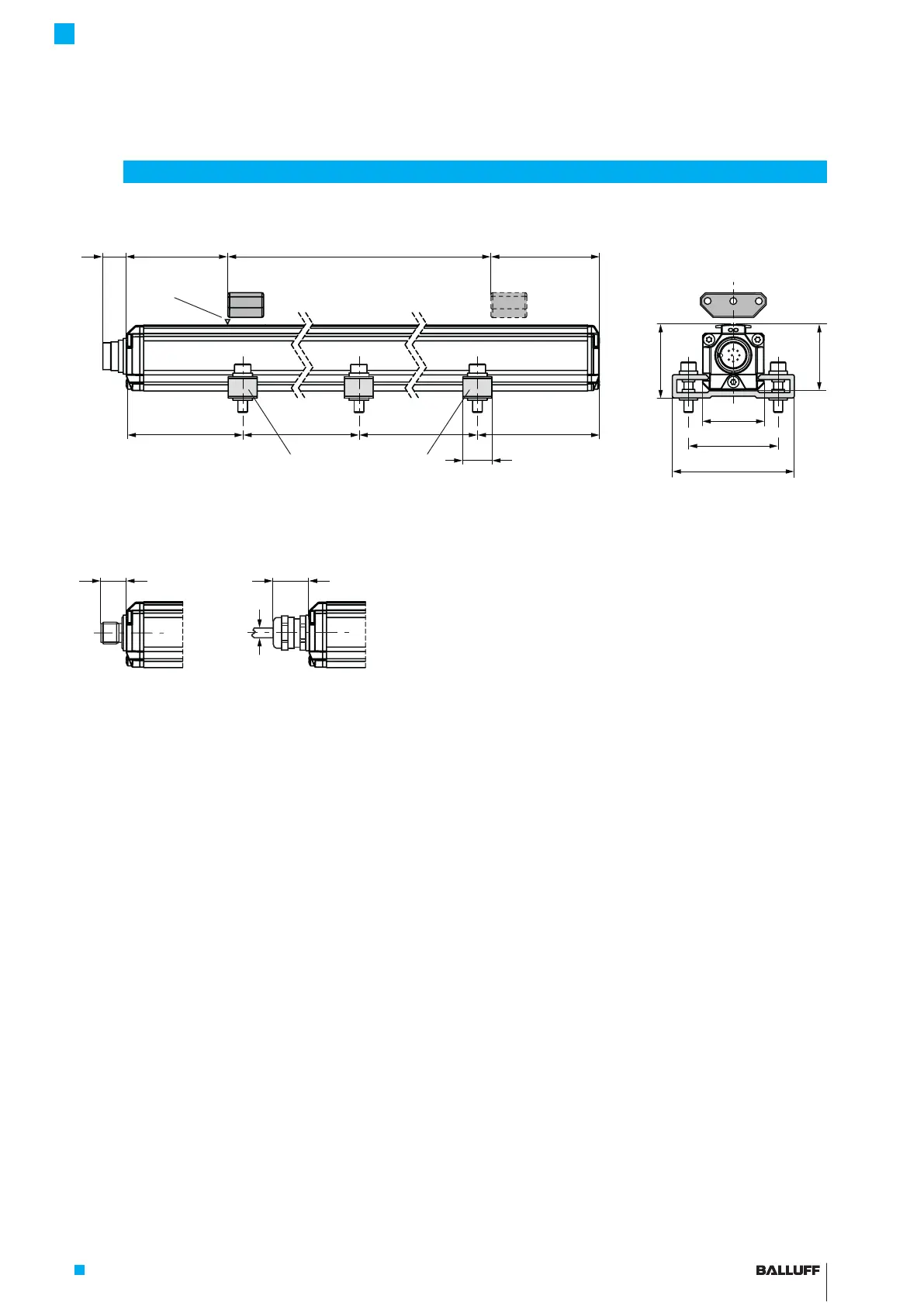
Fig. 3-1: BTL7… transducer, construction
3.1 Construction
Electrical connection: The electrical connection is made
via a cable or a connector (see Type code breakdown from
page
22
).
Housing: Aluminum housing containing the waveguide
and processing electronics.
Magnet: Defines the position to be measured on the
waveguide. Magnets are available in various models and
must be ordered separately (see Accessories starting on
page18).
Nominal length: To optimally adapt the transducer to the
application, nominal lengths from 50mm to 7620mm are
available.
3
Construction and function
~80 ~80~250 ~250
15
50
35
68
~23
13.8
max. 7
41
36.8
1) Unusable area
2) Not included in scope of delivery
1)
Nominal length =
Measuring range
Magnet
BTL5-P-3800-2
1)
Mounting clamps with insulating bushes
and ISO4762M5x22 cylinder-head screws,
max. tightening torque 2Nm
2)
2)
BTL7… cable
BTL7…-S32 View from above on
BTL7…-S32
BTL7…-S115
Groove
BTL7-P511 -M ____ -P-S32/S115/KA_ _
Micropulse Transducer in a Profile Housing
 Loading...


