www.balluff.com 11english
4.4 Electrical connection
Depending on the model, the electrical connection is made
using a cable or a connector.
The connection or pin assignments for the respective
version can be found in Tab. 4-3 to Tab. 4-4.
Note the information on shielding and cable
routing on page12.
4.4.1 Connector S32/cable
Pin Cable color Interface
BTL7-P511…-S32
1
YE yellow
+Init
2
GY gray
+Start/stop
3
PK pink
–Init
4
RD red
Not used
1)
5
GN green
–Start/Stop
6
BU blue
GND
7
BN brown
10…30V
8
WH white
Not used
1)
1)
Unassigned leads can be connected to the GND on the controller side
but not to the shield.
Tab. 4-3: Connection assignments
Fig. 4-9:
Pin assignment of S32 (view from above on transducer),
8-pin M16 circular plug
4
Installation and connection (continued)
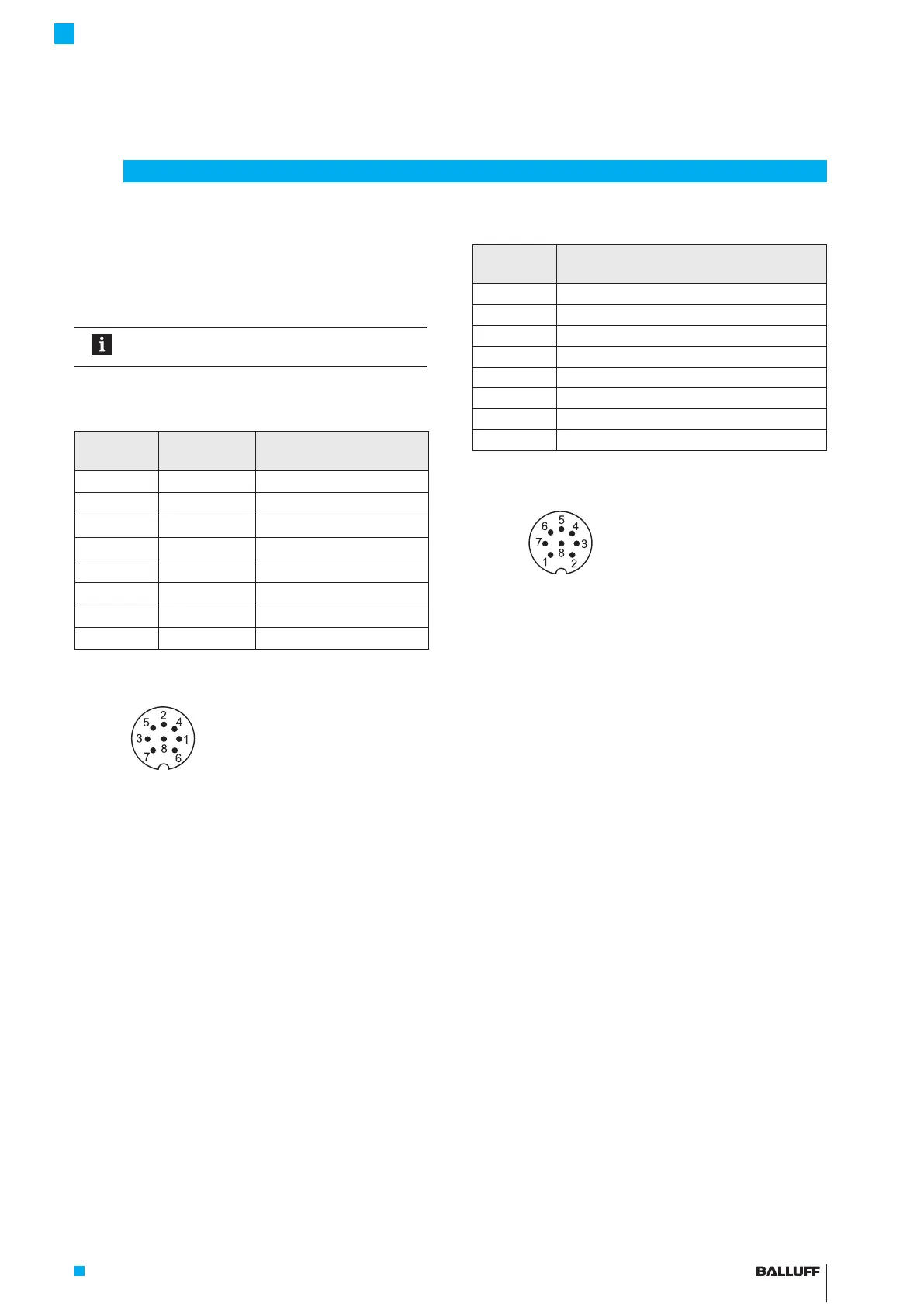
4.4.2 Connector S115
Pin Interface
BTL7-P511…-S115
1 +Init
2 +Start/stop
3 –Init
4 Not used
1)
5 –Start/Stop
6 GND
7 10…30V
8 Not used
1)
1)
Unassigned leads can be connected to the GND on the controller side
but not to the shield.
Tab. 4-4: Connection assignments
Fig. 4-10:
Pin assignment of S115 (view from above on transducer),
8-pin M12 circular plug
BTL7-P511 -M ____ -P-S32/S115/KA_ _
Micropulse Transducer in a Profile Housing
 Loading...


