10 english
3
Construction and function (continued)
3.2 Function
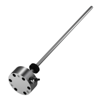
The BTL contains the waveguide which is protected by an
outer stainless steel tube (rod). A magnet is moved along
the waveguide. This magnet is connected to the system
part whose position is to be determined.
The magnet defines the position to be measured on the
waveguide.
An internally generated INIT pulse interacts with the
magnetic field of the magnet to generate a torsional wave
in the waveguide which propagates at ultrasonic velocity.
The component of the torsional wave which arrives at the
end of the waveguide is absorbed in a damping zone to
prevent reflection. The component of the torsional wave
which arrives at the beginning of the waveguide is
converted by a coil into an electrical signal. The travel time
of the wave is used to calculate the position. Depending
on the version, this information is made available as a
voltage or current with rising or falling gradient.
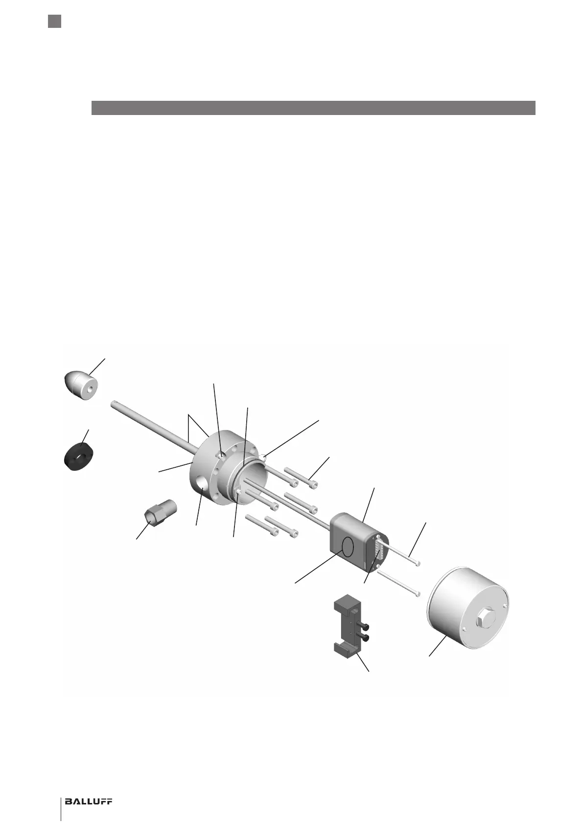
Component overview
Housing cover
Electronics module (including measuring range)
Pressure housing
Conduit entry
4)
Calibration device
7)
Connection terminal
6)
Retaining screws
Housing screws
5)
Float
1)
Magnet
2)
O-ring flange (not
visible)
External housing GND
Internal housing GND
Housing cover
O-ring
Adapter
3)
Cover secondary retaining
screw
Location of
order code for
replacement
electronics module
1) For use in liquid-level applications,
not included in scope of delivery (see Section 12.1 Floats)
2) Not included in scope of delivery (see Section 12.2 Magnets)
3) 1/2"-14 NPT to M20, optional (see Section 12.5 Conduit adapter)
4) Modified 1/2"-14 NPT according to FM 3615, 3.3.3, D, 1
5) M6x45 A4 hexagon socket screws (6x, included)
(replacement screw kit: BTL7-A-FK01-E-J-DEX).
6) Wiring information (see Section 4.5 Electrical connection)
7) Optional (see Section 12.3 Calibration device)
BTL7-A/C/E/G5_ _-M_ _ _ _-J-DEXC-TA12
Magnetostrictive Linear Position Sensor – Rod Style
Type of protection “db” and “ta”
Flameproof enclosure
 Loading...