www.balluff.com 11english
4.4 Electrical connection
Depending on the model, the electrical connection is made
using a cable or a connector.
The connection or pin assignments for the respective
version can be found in Tables 4-3 and 4-4.
Note the information on shielding and cable
routing on page12.
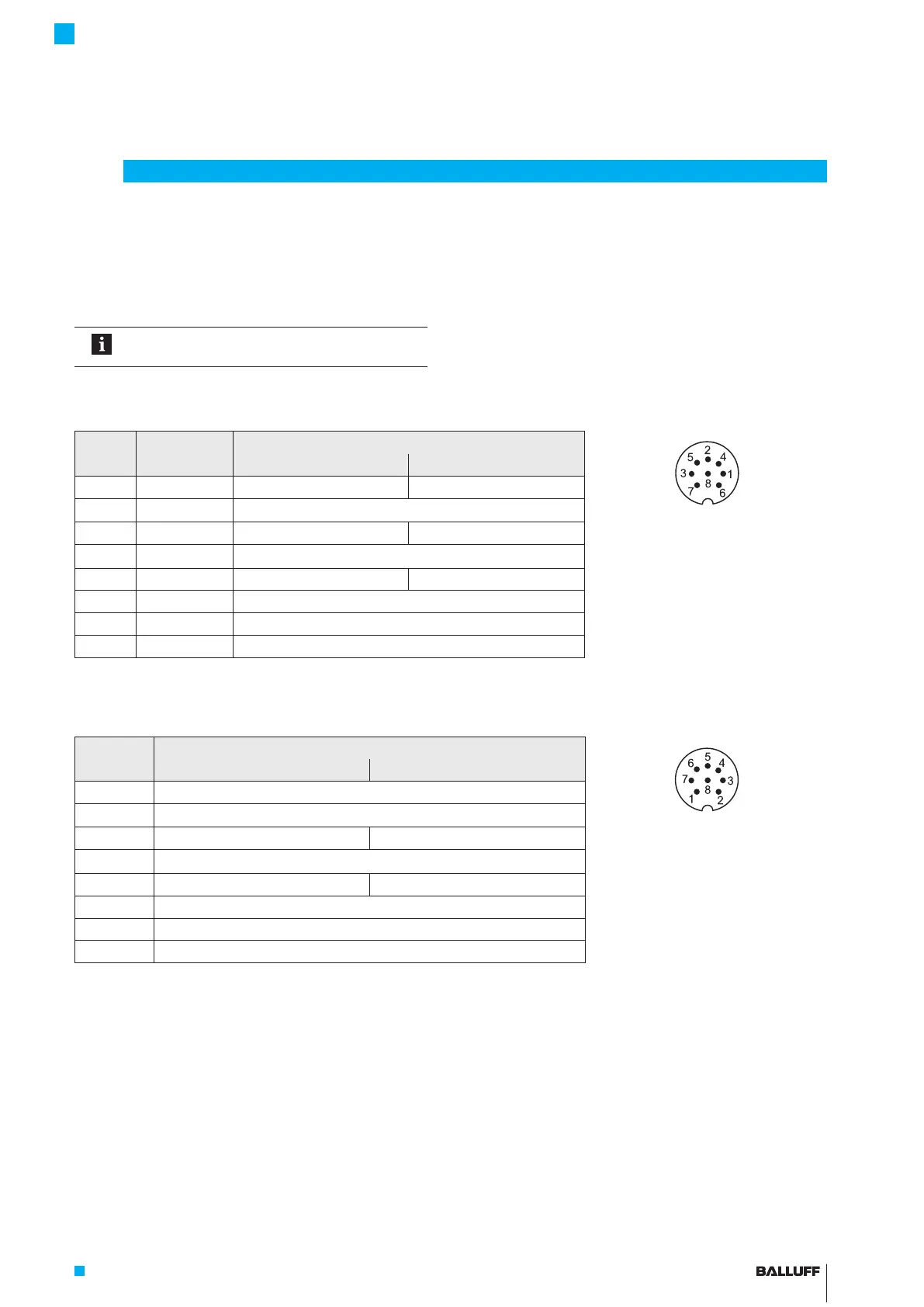
4.4.1 Connector S32/cable connection KA_ _
S32
Pin
KA
Cable color
BTL7-… interface
Fig. 4-9: Pin assignment of S32 connector
(view of connector pins of
transducer)
-A501 -E501
1 YE yellow Not used
1)
4…20mA
2)
(output1)
2 GY gray 0V
3 PK pink 10…0V
2)
(output2) 20…4mA
2)
(output2)
4 RD red La (communication line)
5 GN green 0…10V
2)
(output1) Not used
1)
6 BU blue GND
3)
7 BN brown 10…30V
8 WH white Lb (communication line)
Tab. 4-3: Pin assignment of connector S32/KA_ _
4.4.2 Connector S115
S115
Pin
BTL7-… interface
Fig. 4-10: Pin assignment of S115
connector (view of connector
pins of transducer)
-A501 -E501
1 0V (pin 3)
2 0V (pin 5)
3 10…0V
2)
(output2) 20…4mA
2)
(output2)
4 La (communication line)
5 0…10V
2)
(output1) 4…20mA
2)
(output1)
6 GND
3)
7 10…30V
8 Lb (communication line)
Tab. 4-4: Pin assignment of connector S115
4
Installation and connection (continued)
1)
Unassigned leads can be connected to the GND on the controller side but not to the shield.
2)
Factory setting, can be freely configured with the PC software.
3)
Reference potential for supply voltage and EMC-GND.
BTL7-A/E501-M _ _ _ _ -P-S32/S115/KA _ _
Micropulse Transducer in a Profile Housing

 Loading...


