14 english
6.1 Value table for factory setting
Output gradient Transducer Unit Min. value Nullvalue End value Max. value Error value
Rising
(output1)
BTL7-A… V −0.5 0 +10.0 +10.5 +10.5
BTL7-E… mA 3.6 4.0 20.0 20.4 3.6
Falling
(output2)
BTL7-A… V +10.5 +10.0 0 −0.5 −0.5
BTL7-E… mA 20.4 20.0 4.0 3.6 3.6
Tab. 6-1: Value table for factory settings
NOTICE!
Interference in function
Configuration with the Micropulse Configuration Tool
while the system is running may result in malfunctions.
► Stop the system before configuration.
6.2 Micropulse Configuration Tool
The BTL7-A/E501-… transducer can be configured quickly
and simply on a PC using the Micropulse Configuration
Tool PC software.
The most important features include:
– Online display of the current position of the magnet
– Graphical support for setting the functions and curves
– Display of information on the connected transducer
– Selectable number formats and units for display
– Resetting to factory settings is possible
– Demo mode without having transducer connected
The PC software and associated
manual can be found in the Internet under
www.balluff.com.
6
Configuration with the Micropulse Configuration Tool
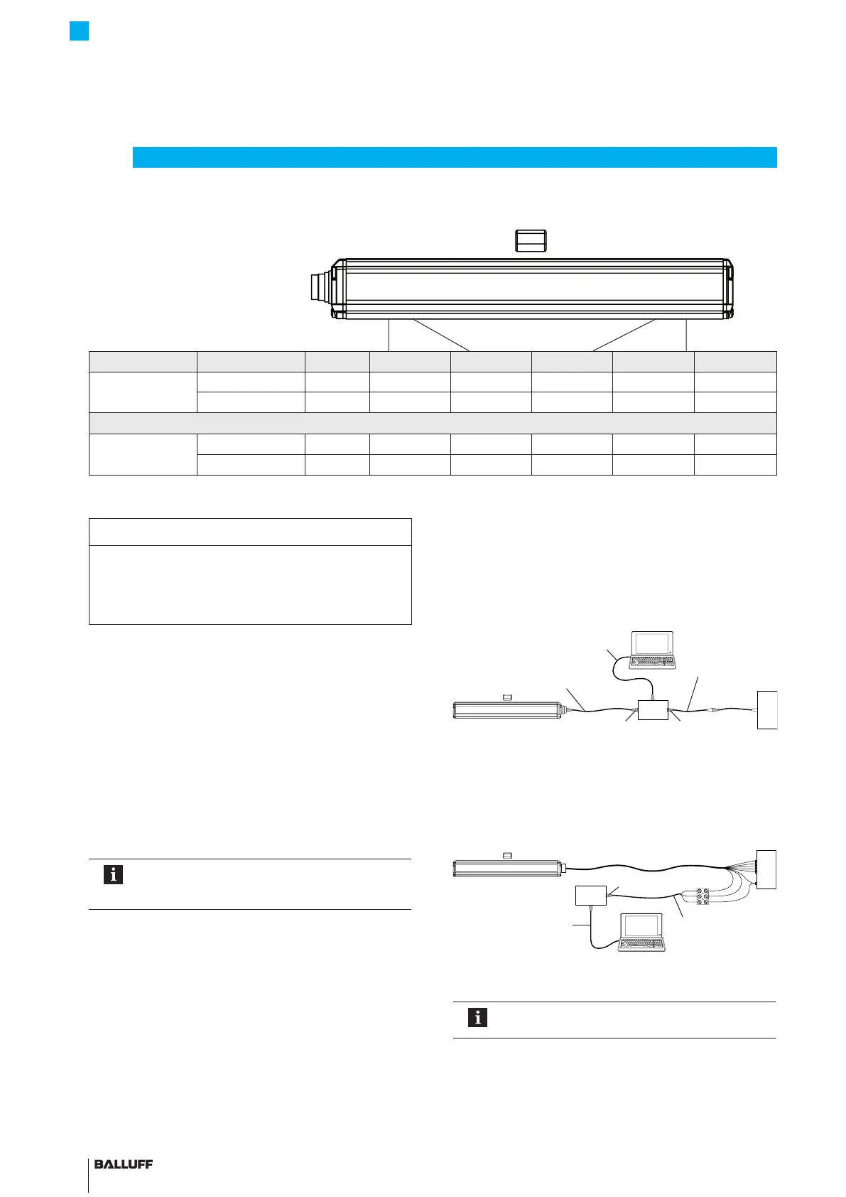
6.3 Connecting the USB communication box
With BTL7-A/E501-… transducers with connectors (S32/
S115), the communication box must be looped in between
the transducer and controller. The communication box is
connected to the PC via a USB cable.
Fig. 6-1: Connecting the communication box with a connector
With a BTL7-A/E501-…-KA_ _ transducer, the
communication lines La, Lb and GND must be connected
to the USB communication box.
Fig. 6-2: Connecting the communication box with a cable connection
When reading or writing data via the
Configuration Tool, both LEDs flash green.
USB cable
6-pin8-pin
Connection cable approx. 0.3m with
S32 or S115 (female) connector
Connection cable
approx. 0.3m with
S32 or S115 (male)
connector
Controller
Controller
USB cable
8-pin
Connection cable
approx. 0.6m with
luster terminal
BTL7-A/E501-M _ _ _ _ -P-S32/S115/KA _ _
Micropulse Transducer in a Profile Housing

 Loading...


