22 english
9
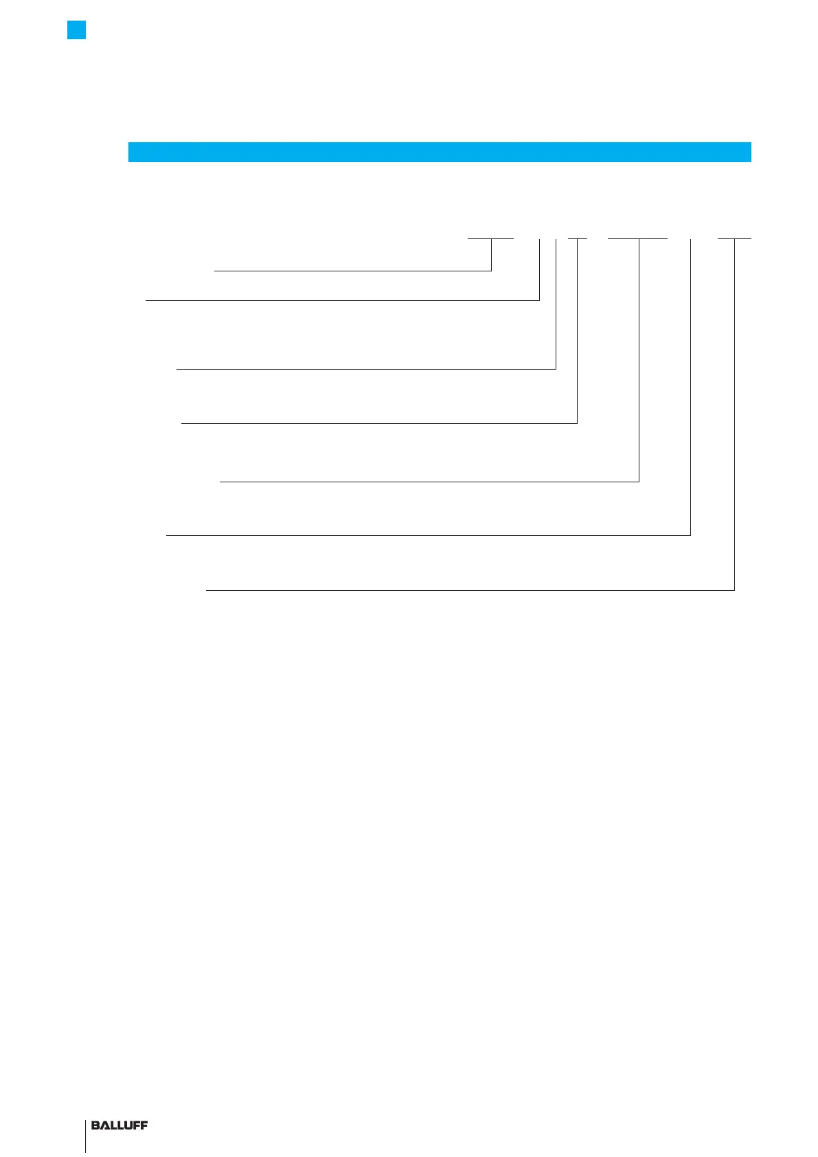
Type code breakdown
BTL7 - A 5 01 - M0500 - P - S32
Micropulse transducer
Interface:
A = Analog interface, voltage output 0 to 10V/10 to 0V (factory setting)
E = Analog interface, current output 4 to 20 mA/20 to 4mA (factory setting)
Supply voltage:
5 = 10…30VDC
Output gradient:
01 = 2 outputs, configurable
Nominal stroke (4-digit):
M0500 = Metric specification in mm, nominal length 500mm (M0050…M7620)
Construction:
P = profile housing
Electrical connection:
S32 = 8-pin, M16 plug per IEC 130-9
S115 = 8-pin, M12 plug
KA05 = Cable, 5 m (PUR)
BTL7-A/E501-M _ _ _ _ -P-S32/S115/KA _ _
Micropulse Transducer in a Profile Housing

 Loading...


