www.balluff.com 23english
b
a
b
8
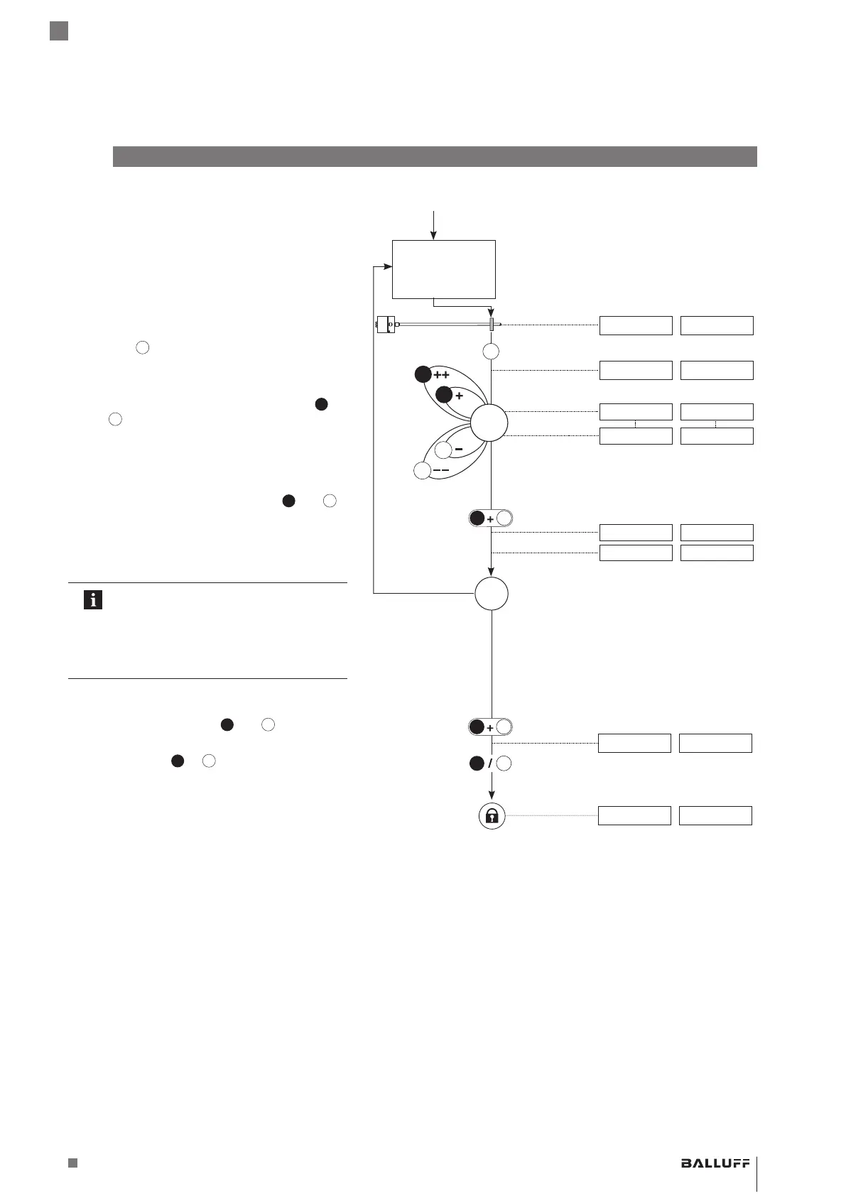
Adjusting (continued)
Adjust
start value
(See page22)
Displayed values (example)
At 0 to 10 V At 4 to 20 mA
4. Adjust end value
► Bring magnet to end position.
9.89 V 19.13 mA
► Activate
for at least 2s.
> 2s
⇒ Indication for “Adjust end value” is displayed.
10.00 V 20.00 mA
► Adjust end value
⇒ The end value can be changed using
and
1)
. The gradient of the output is changed,
but the null value remains unchanged (see
page18).
9.89 V 19.13 mA
9.00 V 19.00 mA
► Exit calibration procedure: Activate
and
for
no more than 2 s.
< 2s
a
b
⇒ Indication for “Adjustment” is displayed.
2.00 V 6.00mA
⇒ Set position value is saved.
9.00 V 19.00 mA
Check values
The settings for the start value and end
value have a mutual effect depending
on the measuring position.
Repeat steps 3 and 4 until the desired
values are exactly set.
5. Exit adjustment and deactivate buttons
► Simultaneously activate
and
for at least 6 s.
> 6s
a
b
⇒ Output indicates error value.
10.50 V 3.60 mA
► Briefly activate
or
(< 1 s).
< 1s
b
⇒ Buttons are deactivated.
⇒ Current position value is displayed.
9.00 V 19.00 mA
1) Briefly activate button: Current value is increased or
decreased by approx. 1mV or 1 µA.
If a button is activated longer than 1 s, the step interval is
increased.
BTL7-A/C/E/G5_ _-M_ _ _ _-J-DEXC-TA12
Magnetostrictive Linear Position Sensor – Rod Style
Type of protection “db” and “ta”
Flameproof enclosure