www.balluff.com 2
No. 880278 EN · A16; Subject to modification. Replaces edition 1206.
english
Only use the proper nut for the mounting thread. Firmly
tighten the transducer with a maximum torque of 100Nm.
Radial cable outlet
During installation, the direction of the cable
outlet is specified by the thread.
For horizontal assembly with nominal lengths > 500 mm,
support the rod and tighten it at the end if necessary (only
possible with a diameter of 10.2mm).
If installed in a hydraulic cylinder, the magnet should not
make contact with the rod. Minimum bore diameter in the
support piston:
Rod diameter Bore diameter
10.2mm At least 13mm
8mm At least 11mm
Startup
DANGER
Uncontrolled system movement
When starting up, if the position measuring system is
part of a closed loop system whose parameters have not
yet been set, the system may perform uncontrolled
movements. This could result in personal injury and
equipment damage.
► Persons must keep away from the system's
hazardous zones.
► Startup must be performed only by trained technical
personnel.
► Observe the safety instructions of the equipment or
system manufacturer.
1. Check connections for tightness and correct polarity.
Replace damaged connections.
2. Turn on the system.
3. Check measured values and adjustable parameters
regularly (especially after replacing the transducer or
after repair by the manufacturer). Recalibrate the
transducer, if necessary.
The calibration procedure is described in the
comprehensive user's guide.
Shielding and cable routing
Defined ground!
The transducer and the control cabinet must be
at the same ground potential.
Shielding
To ensure electromagnetic compatibility (EMC), observe
the following:
– Connect the transducer and controller using a shielded
cable. Shielding: Copper filament braided, at least 85%
coverage.
– Connector version: Shield is internally connected to
connector housing.
– Cable version: On the transducer side, the cable
shielding is connected to the housing. Ground the
cable shielding on the controller side (connect with the
protective earth conductor).
Magnetic fields
The position measuring system is a magnetostrictive
system. It is important to maintain adequate distance
between the transducer cylinder and strong, external
magnetic fields.
Cable routing
Do not route the cable between the transducer, controller,
and power supply near high voltage cables (inductive stray
noise is possible). The cable must be routed tension-free.
Cable length
BTL7-A/G Max. 30 m1)
BTL7-C/E Max. 100 m1)
1) Prerequisite: Construction, shielding and routing preclude the effect of
any external noise fields.
Installation
NOTICE!
Interference in function
Improper installation can compromise the function of the
transducer and result in increased wear.
► The mounting surface of the transducer must make
full contact with the supporting surface.
► The bore must be perfectly sealed (O-ring/flat seal).
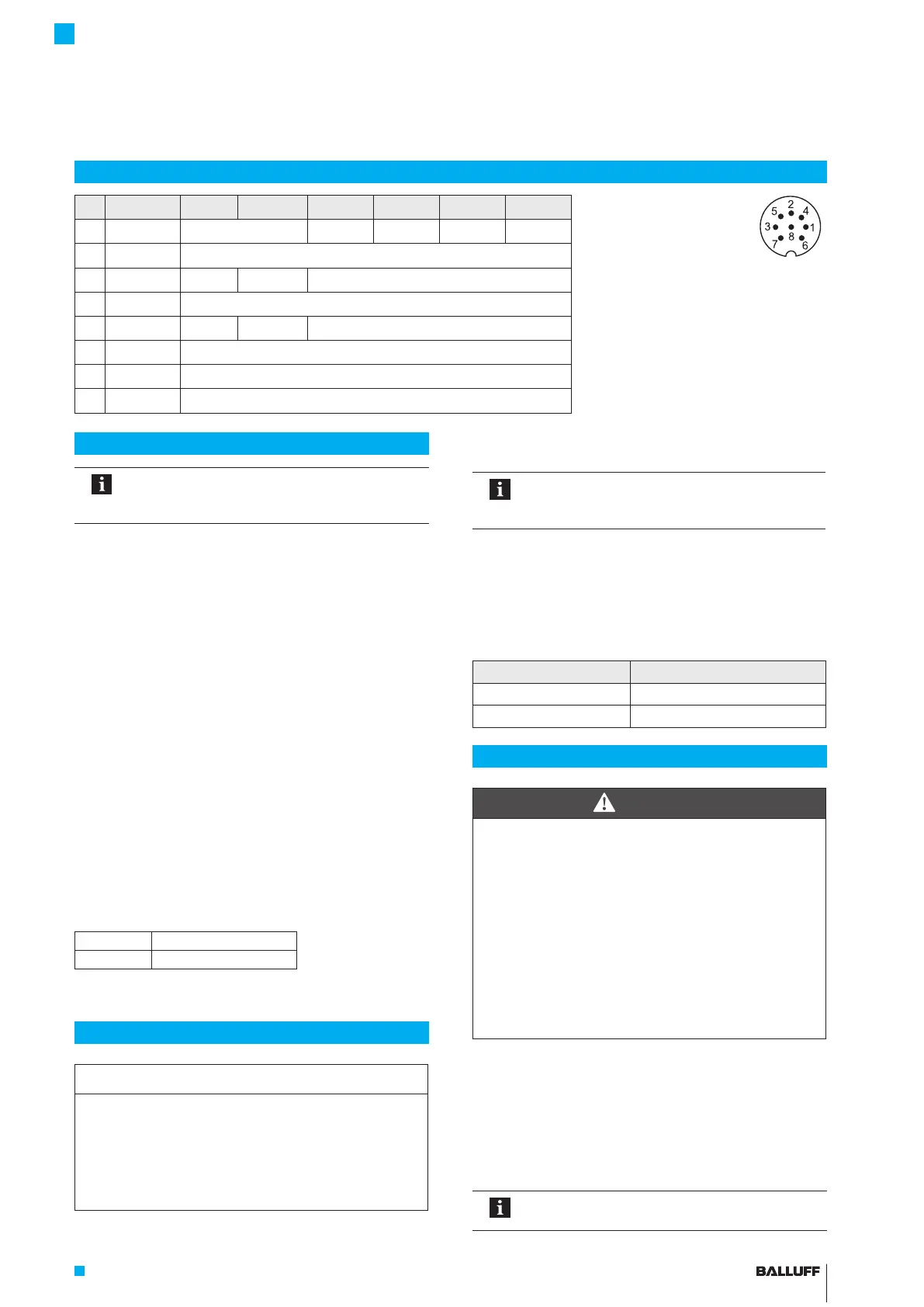
Electrical connection
Pin Cable color -A510 -G510 -C500 -C570 -E500 -E570
Pin assignment of S32 (view of
connector pins of transducer),
8-pin M16 circular plug
1 YE yellow Not used 1) 0…20 mA 20…0 mA 4…20 mA 20…4 mA
2 GY gray 0 V
3 PK pink 10…0V 10…-10V 10…0V 3)
1) Unassigned leads can be connected to GND
on the controller side but not to the shield.
2) Reference potential for supply voltage and
EMC-GND.
3) The voltage outputs may exhibit a minimal
offset to the harmonized current output.
4 RD red La (programming input)
5 GN green 0…10V -10…10V 0…10V 3)
6 BU blue GND 2)
7 BN brown 10…30V
8 WH white Lb (programming input)
BTL7-A/C/E/G5 __ -M ____ -H/W(8)-S32/___
Micropulse Transducer - Rod Style
 Loading...


