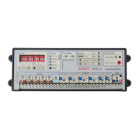
Description:
Alarm panel connections:
- 12 V supply: possibly through fuse 1 AT.
- Monitoring output: the output relay is open as long as the alarm panel is
not monitoring and closed as long as it is in monitoring mode.
- Alarm output: the output relay is open as long as the alarm panel is not
in an alarm condition and switches to closed when in alarm.
- Tamper: Tamper is detected when the loop is interrupted.
- Dialler input 1: OKout output: Technical failures / problems are reported
to the dialler when NO contact opens.
- Dialler input 2: Empty fog cartridge or "no power to fog generator".
Both problems are reported together to the dialler when one or both
NO contact ([Empty] or [Power]) opens.
PIR Confirmation sensor:
A typical PIR or better dual-technology (PIR / radar) sensor.
Objective: To delay the alarm status until a local zone detector confirms the
burglary signal of the alarm locally. The connected PIR / radar detector will
then open its contacts and the 12 VDC on the confirmation input [Conf.] is
removed, and consequently the alarm mode is confirmed.
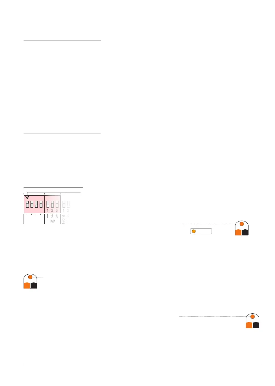
Dip switch settings:
Dip G: is ON = the controller and the fog generator
are in monitoring mode [Guard] as long as there is
12 VDC provided to the Guard input [Guard].When
the controlling alarm system's monitoring contact closes,
the orange Guard LED will light
and BANDIT is in monitoring status .
Dip A: is ON = the controller and the fog generator are in alarm mode
(Incl. fog ejection) as long as there is 12VDC provided to the alarm
input [Alarm].
So when the alarm system closes its alarm contact, the orange Alarm
LED will light and BANDIT is in the alarm status until removal of the
monitoring status.
Dip C: is OFF = when the connected sensor remains inactive, its alarm
contacts are closed, so there is 12 VDC on the Confirmation
input [Conf.] and the orange LED Conf. is lit
When the sensor detects motion, it opens its alarm contacts
and so removes the 12 over [Conf.], so confirmation toVDC
switch to the alarm mode.
Conf.
C+ C-
Alarm
A+ A-
Guard
G+ G-
1 2 3 4 1 2 3 1 21 2 3 4 1 2 3 1 2
Front
Inputs
M³
G
A
C
F
2
3
X1
1 2 3 4 1 2 3 1 2
GuardGuard
BANDIT Controller CF31 v2 / Manual v.102
Installation example 2 - p. 35