Installation example 3 - p. 37
Description:
Alarm panel connections:
- 12V supply: Eventually via fuse of 1AT
- Sabotage loop: Sabotage is detected once the loop is interrupted.
- Dialler input 1: OKout output: Technical failures / problems are reported
to the dialler when NO contact opens.
- Dialler input 2: Empty fog cartridge or "no power to fog generator".
Both problems are reported together to the dialler when one or both
NO contact ([Empty] or [Power]) opens.
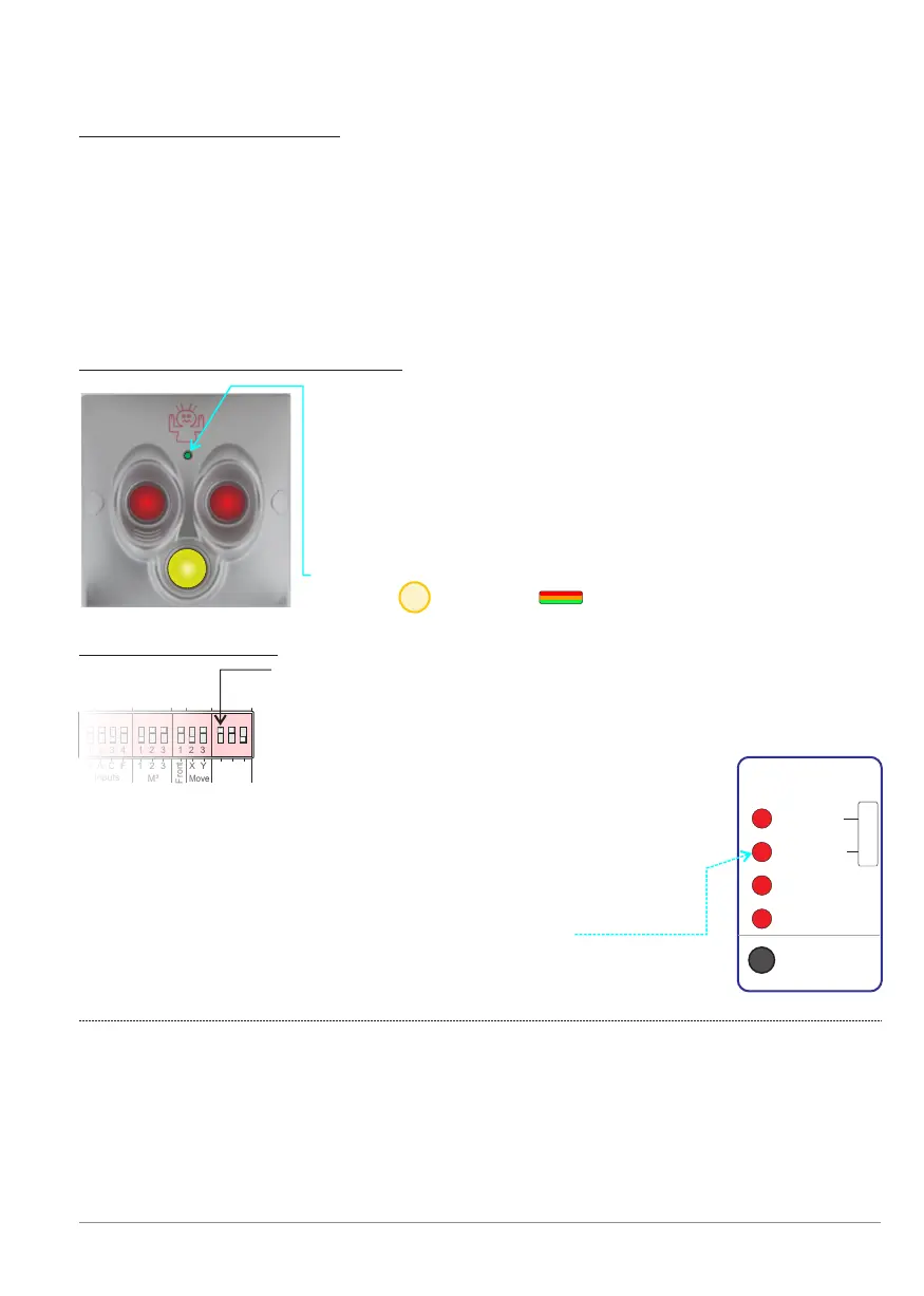
Panic button: BANDIT 820-13S:
Dip switch settings:
Dip [PanBut.] 1 is ON = BANDIT panic button attached.
The dip’s [PanBut.] 2 ON and 3 OFF = background lighting
of panic button 50% dimmed. More info: see p. 10.
1 2 3 4 1 2 3 1 2 3 1 2 31 2 3 4 1 2 3 1 2 3 1 2 3
Front
Inputs
M³
Move
PanBut.
G
A
C
F
2
3
1 2
3
X Y 1
1 2 3 4 1 2 3 1 2 3 1 2 3
Settings:
Once Dip[PanBut] 1 is read as ON, the controller will
assume that there is a Bandit panic button connected.
This is why the controller also controls the connection
to, and the working of the panic button.
When an error occurs this is displayed via:
See also p. 15.
F
Cover
Moved
PanBut.
To Fog
Tamper
Reset
Comm.
!
BANDIT Controller CF31 v2 / Manual v.102
- Once the two red push buttons are simultaneously
pushed in, panic mode will start (see also p.11)
- As long as the yellow button is pushed in, the built-in
buzzer of the fog generator will buzz. This function is
intended to draw the attention of employees who are
in close proximity.
- The three colour infoLed displays the same as the
Status front Led . See also p. 27.
Front
21