4 Controller Connections
To connect IO-Link devices on machines in industrial environments, an M12 quick disconnect connection is typically used.
The pin assignment is according IEC 60974-5 is the following:
• Pin 1: 24 V DC
• Pin 2: Switching Digital I/O (PNP only)
• Pin 3: 0 V
• Pin 4: Switching Digital I/O (NPN, PNP, or Push-Pull) and IO-link Communication Line
Figure 9. IO-Link pin assignments
1
L+
C/Q
L-
3
2
4
IO-Link Mode (process data)
Digital I/O (DIO) Mode (ON/OFF data)
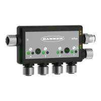
Figure 10. DXMR90-4K IO-Link Master ports
M12 Power Port/
Configurable Modbus Port 0
(male)
Configurable
Modbus
Port 0
(female)
D-coded Ethernet
(female)
IO-Link Master
Ports 1-4
(female)
One male M12 connection provides common power and ground to all M12 IO-Link ports. One 100 Mbps Ethernet port
(female) uses an M12 D-coded Ethernet connection.
• Modbus TCP
• EtherNet/IP
• Configuration/discovery port
Four IO-Link controller connections using female M12 connectors.
• Separate IO-Link control and programmability for each connection point
• Configurable SIO mode on Input 1 and Input 2 of each IO-Link port
The DXMR90-4K IO-Link Master has 4 Class A ports. Pin 2 on these is an additional discrete IO channel. For specific pinout
connections, see Wiring on page 8.
For more information on the device registers and port settings of the DXMR90-4K IO-Link Master, refer to the DXMR90-4K
IO-Link Master Device Register Map (p/n 229732).
4.1 Ethernet
Before applying power to the DXMR90-4K, verify the Ethernet cable is connected.
The Ethernet connection supports the DXM Configuration Software, Modbus/TCP, and EtherNet/IP. ScriptBasic also has
access to Ethernet for custom programming. Use the software to configure the characteristics of the Ethernet connection,
including the IP address. Any parameters not changeable from the menu system are configurable from the configuration
software.
4.2 Internal Local Registers (Slave ID 199)
The main storage elements for the DXMR90-4K are its Local Registers, which can store 4-byte values that result from
register mapping, action rules or ScriptBasic commands.
For more information on the device registers and port settings of the DXMR90-4K IO-Link Master, refer to the DXMR90-4K
IO-Link Master Device Register Map (p/n 229732).
DXMR90-4K IO-Link Master
14 www.bannerengineering.com - Tel: + 1 888 373 6767
 Loading...