Register Definition
2x023 Socket x Rule 0 receives
2x025 Socket x Rule 0 timeouts
2x027 Socket x Rule 0 broadcasts
2x029 Reserved
2x031 Socket x Rule 1 transmits
2x033 Socket x Rule 1 receives
2x035 Socket x Rule 1 timeouts
2x037 Socket x Rule 1 broadcasts
2x039 Reserved
Reset Codes—The reset codes are in virtual register 11015 and define the condition of the last restart operation.
Table 7: Reset codes
Reset Code
Definition
0 Undefined
1 Unknown
2 General
3 Brownout
4 Watchdog
5 User
6 Software
7 Return from backup mode
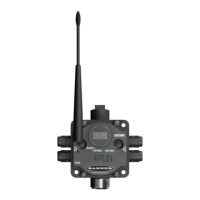
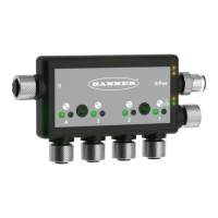
4.3 Connecting to Remote IO-Link Devices
The DXMR90-4K has four IO-link ports for connecting IO-Link devices and digital sensors, lights, and actuators. All ports use
a 4-pin M12 female connector to connect to remote devices. No additional wiring is required if the sensors use compatible
wiring.
Table 8: Ports 1-4 female connector
Port 1–4 5-pin M12 Connector (female)
Pin Wire Color Description
1 Brown (bn) 18 V DC to 30 V DC
2 White (wh) I/Q (digital in-out)
3 Blue (bu) DC common (GND)
4 Black (bk) C/Q (communications/digital in-out)
5 Gray (gy) Not used/reserved
The basic communications parameters for the IO-Link ports are set in the DXM Configuration Software and are saved in the
XML configuration file. Each port can have unique settings.
DXMR90-4K IO-Link Master
www.bannerengineering.com - Tel: + 1 888 373 6767 17
 Loading...