3 Quick Start Guide
3.1 Apply Power to the Controller
Follow these instructions to apply 12–30 V DC power to the DXMR90-4K using a wall plug.
Required equipment:
• DXMR90-4K IO-Link Master
• PSW-24-1 Wall plug power supply; 24 V DC, 1 A (or equivalent 24 V DC M12 power supply)
1. Connect the PSW-24-1 power supply to the male M12 connector on the DXMR90-4K, Port 0.
2. Plug in the PSW-24-1 wall plug power supply.
3.1.1 Wiring
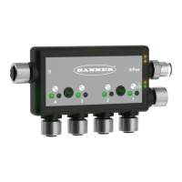
Figure 3. DXMR90-4K IO-Link Master ports
M12 Power Port/
Configurable Modbus Port 0
(male)
Configurable
Modbus
Port 0
(female)
D-coded Ethernet
(female)
IO-Link Master
Ports 1-4
(female)
Table 1: Ports 1-4 female connector
Port 1–4 5-pin M12 Connector (female)
Pin Wire Color Description
1 Brown (bn) 18 V DC to 30 V DC
2 White (wh) I/Q (digital in-out)
3 Blue (bu) DC common (GND)
4 Black (bk) C/Q (communications/digital in-out)
5 Gray (gy) Not used/reserved
Table 2: Port 0 male connector
Port 0 4-pin M12 Connector (male)
Pin Wire Color Description
1 Brown (bn) 18 V DC to 30 V DC
2 White (wh) RS485 / D1 / B / +
3 Blue (bu) DC common (GND)
4 Black (bk) RS485 / D0 / A / -
Table 3: Port 0 female connector
Port 0 4-pin M12 Connector (female)
Pin Wire Color Description
1 Brown (bn) 18 V DC to 30 V DC
2 White (wh) RS485 / D1 / B / +
3 Blue (bu) DC common (GND)
4 Black (bk) RS485 / D0 / A / -
DXMR90-4K IO-Link Master
8 www.bannerengineering.com - Tel: + 1 888 373 6767
 Loading...