TL50 Basic Wireless Andon Tower Light Instruction Manual
December 19, 2023 page3
LED Behavior for the One LED Nodes
Nodes do not sample inputs until they are communicating with the Gateway. The radios and antennas must be a minimum distance apart to
function properly. Recommended minimum distances are:
900MHz150mWand250mWradios:6feet
900MHz1Wattradios:15feet
2.4GHz65mWradios:1foot
LED(Bi-color) NodeStatus
Flashinggreen Radiolinkokay
Greenandredflashingalternately InBindingmode
Bothcolorsaresolidfor4seconds,thenflash4times;looksamber Bindingmodeiscomplete
Flashingred,onceevery3seconds Radiolinkerror
Flashingred,onceeverysecond Deviceerror
LCA130T Modbus Registers
Holding registers
Modbus Registers EIP Registers
I/O Type
I/O Range
Holding Register
Representation (DEC)
Gateway Node Node Min Max Min Max
1 1 + (Node# x 16) 0 + (Node# x 8)
Instance 100 / N7
Bit Packed Input* 0 682 0 682
2 2 + (Node# x 16) 1 + (Node# x 8) Button 1 Input 1 0 2 0 2
3 3 + (Node# x 16) 2 + (Node# x 8) Button 2 Input 2 0 2 0 2
4 4 + (Node# x 16) 3 + (Node# x 8) Button 3 Input 3 0 2 0 2
5 5 + (Node# x 16) 4 + (Node# x 8) Button 4 Input 4 0 2 0 2
6 6 + (Node# x 16) 5 + (Node# x 8) Button 5 Input 5 0 2 0 2
7 7 + (Node# x 16) 6 + (Node# x 8) Reserved
8 8 + (Node# x 16) 7 + (Node# x 8) Device Message
9 9 + (Node# x 16) 8 + (Node# x 8)
Instance 112 / N14
Bit Packed Output* 0 682 0 682
10 10 + (Node# x 16) 9 + (Node# x 8) Button 1 Output 1 0 2 0 2
11 11 + (Node# x 16) 10 + (Node# x 8) Button 2 Output 2 0 2 0 2
12 12 + (Node# x 16) 11 + (Node# x 8) Button 3 Output 3 0 2 0 2
13 13 + (Node# x 16) 12 + (Node# x 8) Button 4 Output 4 0 2 0 2
14 14 + (Node# x 16) 13 + (Node# x 8) Button 5 Output 5 0 2 0 2
15 15 + (Node# x 16) 14 + (Node# x 8) Control Message 0 2 0 2
16 16 + (Node# x 16) 15 + (Node# x 8) Reserved 0 2 0 2
*Bit-packedregistercontentsfordefininglightbehavior
Register contents summed to define the light behavior
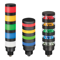
Light (top to bottom) Solid light Flashing light
Light 5 1 2
Light 4 4 8
Light 3 16 32
Light 2 64 128
Light 1 256 512
The light is solid when the button is pressed and released. The light flashes when the button is pressed and held. Combinations of button
presses and holds are summed.
For example, the value held in register 1 is 6 (2 + 4) when button 5 is flashing (2) and button 4 (4) is solid.
Specifications
SupplyVoltageandCurrent
18VDCto30VDC
© Banner Engineering Corp. All rights reserved.