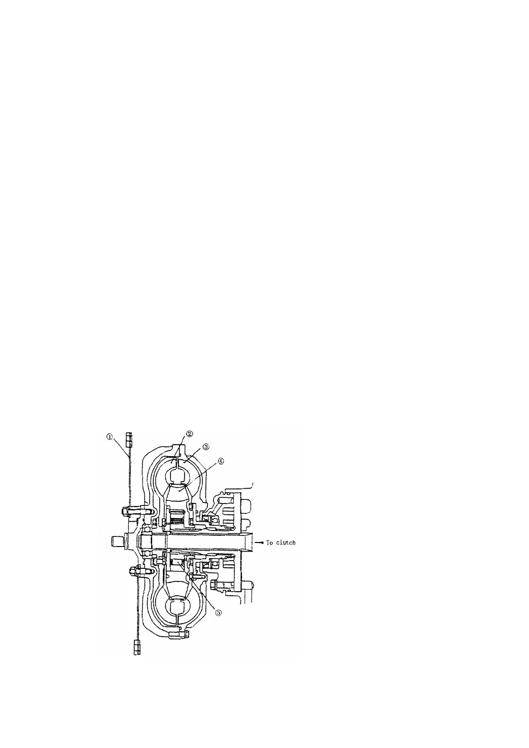
2.3 Torque converter (Fig2.3)
The torque converter mainly consists of an impeller, a turbine and an idler pulley.
The liquid, from the impeller driven by an input shaft, is jetted along its leaves to
leaves of the turbine to transmit the torque to the output shaft (Mechanical energy is
changed into kinetic one). And the flowing direction of the liquid from the turbine wheel is
changed by the idler pulley to cause partial liquid return the impeller at an angle and
produce so large reaction torque driving the idler pulley that the value of output torque is
more than that of input torque by the value of the reaction torque. When the turbine speed
keeps on increasing up to speed of the impeller, the change rate of the flow angle slows
down and the value of the output torque keeps on decreasing until the liquid flows into the
leaves of the idler pulley in opposite direction. When original reaction torque acts in the
opposite direction, the torque value of the output shaft is less than that of the input shaft.
To prevent this, a one-way clutch is fitted in the idler pulley, causing the idler pulley freely
rotate on this case. The way of torque-converting can be used to ensure efficient and
smooth work of the torque converter.
The torque converter, filled up with the torque converter oil, in the drive unit is driven
by an engine through a spring plate and flywheel on the engine. A charging pump is
driven by a driving gear which is supplied by the pump. The power is transmitted to the
transmission through a turbine shaft spliced to the turbine.
Fig 2.3 Torque converter


 To Next Page