11
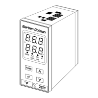
B.2) Inductive loads
High voltage transients can occur when switching
inductive loads. It is recommended to install an additional
RC network across the internal contacts as shown.
The same problem can occur when a switch is used in
series with the internal contacts.
LOAD
C
R
POWER
LINE
It is recommended to install an additional RC network
across the external contacts as close to the instrument
terminals as possible.
The value of capacitor (C) and resistor (R) are shown in
the following table.
C R P Resistor and
Load (µF) (Ω) (W) Capacitor
<40 mA 0.047 100 1/2 260 Vac
<150 mA 0.1 22 2 260 Vac
<0.5 Amp 0.33 47 2 260 Vac
<1 Amp 0.47 47 2 260 Vac
Relay output wiring must be as far away as possible from
input wiring and communication cables.
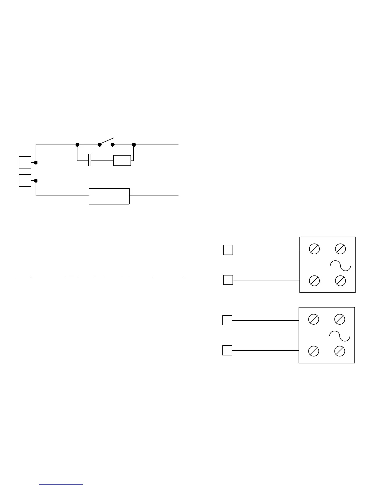
B.3) Voltage outputs for SSR drive
These are time proportioning outputs.
Logic voltage for SSR drive.
Logic status 1: 24 Vdc ±20% @ 1 mA.
14 Vdc ±20% @ 20mA.
Logic status 0: Less than 0.5 Vdc.
NOTES:
1) This output is not isolated. A double or reinforced
isolation between the instrument output and the
power supply must be made by an external solid state
relay.
2) Relay or SSR output must be configured using
jumpers J304 and J305 as shown in the “preliminary
hardware settings.”
18
-
-
+
+
OUT 1
19
Solid State Relay
14
-
-
+
+
OUT 2 (AL1/Cool)
15
Solid State Rela
 Loading...